Functional coatings and designs for medical implants

a technology of functional coating and implants, applied in the field of medical implants, can solve the problems of reducing the effectiveness of implants, counterproductive renarrowing of arteries, and affecting the function of implants, and achieve the effect of enhancing their functionality

Inactive Publication Date: 2005-07-21
BOSTON SCI SCIMED INC
View PDF12 Cites 104 Cited by
  • Summary
  • Abstract
  • Description
  • Claims
  • Application Information

AI Technical Summary

Benefits of technology

[0003] The present invention regards an implant that may be uniquely shaped to enhance its functionality and that may also be coated with a coating system that affects its functionality. In one embodiment the implant may have a first surface that is covered with a filter material, the filter material being in contact with a catalyst that promotes the decomposition of hydrogen peroxide into hydroge

Problems solved by technology

The body's reaction to an implant over time may also, however, be unwanted, reducing the implant's effectiveness.
This renarrowing of the artery is counterproductive as it creates a medical condition much like the arteriosclerosis and hardening of the arteries that the stent was intended to cure.
Further, in still

Method used


Image

  • Functional coatings and designs for medical implants
  • Functional coatings and designs for medical implants
  • Functional coatings and designs for medical implants

Examples


Embodiment Construction

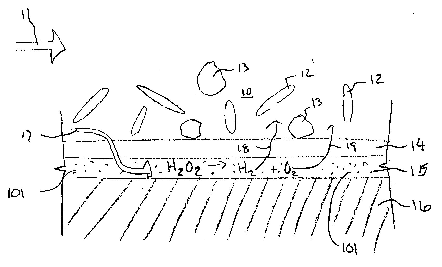
[0016]FIG. 1 is a side sectional view of implant 16 after it has been placed in contact with a moving fluid 10, such as blood, within the body of a patient. The white blood cells 13 and red blood cells 12 of the fluid 10 are clearly labeled in FIG. 1. Also visible in FIG. 1 is the meso-porous layer 14, the catalytic layer 15 of the implant 16, and the therapeutic 101, which is within the catalytic layer 15. The direction of flow of fluid 10, which is blood in this embodiment but may be other fluids as well in this same embodiment and in others, is indicated with arrow 11.

[0017] In the present invention the coating 14 may function to prevent red blood cells 12 and white blood cells 13 from adhering to the implant 16 and from reaching the catalytic layer 15 of the implant 16. Thus, only particles and materials small enough to pass through the meso-porous layer 14 may reach the catalytic layer 15. Once there, the fluid may change under the influence of the catalyst, may come in contac...


PUM

PropertyMeasurementUnit
Areaaaaaaaaaaa
Therapeuticaaaaaaaaaa
Surface areaaaaaaaaaaa

Abstract

The present invention regards an implant that may be uniquely shaped to enhance its functionality and that may also be coated with a coating system that affects its functionality. In one embodiment the implant may have a first surface that is covered with a filter material, the filter material being in contact with a catalyst that promotes the decomposition of Hydrogen Peroxide into Hydrogen and Oxygen. In this and other embodiments, this filter material may be made from ceramic materials and may be meso-porous. In another embodiment, the implant may or may not be coated with this system and may have at least one strut with a tapered cross-section, the cross-section becoming smaller in area when moving from a reference point on the inside of the implant to the outside of the implant.

Description

FIELD OF THE INVENTION [0001] The present invention regards medical implants for implantation within the body of a patient. More specifically, the present invention regards functional designs and functional meso-porous coating systems for implants that may be placed within the body of a patient. BACKGROUND [0002] Medical implants may be natural, synthetic or hybrid materials that are intended to be placed within the body of a patient for prolonged periods of time. An implant may be used to, among other things, support collapsed vessels in the human vasculature, replace missing tissue or bone throughout the body of a patient, and supplement existing tissue, vessels, and structures. Implants may remain within the body of a patient for several days, weeks, and even years. Over time, the body's reaction to the implant can enhance the performance of the implant. For instance, when hard tissue, such as bone, is replaced with an implant, the body may, over time, absorb some or all of the i...

Claims


Application Information

Patent Timeline
IPC IPC(8): A61F2/00A61F2/06A61F2/90A61L27/30A61L27/54A61L27/56A61L31/08A61L31/14A61L31/16
CPCA61F2/91A61F2250/0068A61L2300/606A61L31/146A61L31/16A61L31/082
Inventor WEBER, JANHOLMAN, TOMEIDENSCHINK, TRACEECHEN, JOHN JIANHUA
Owner BOSTON SCI SCIMED INC
Why Eureka
Try Eureka