

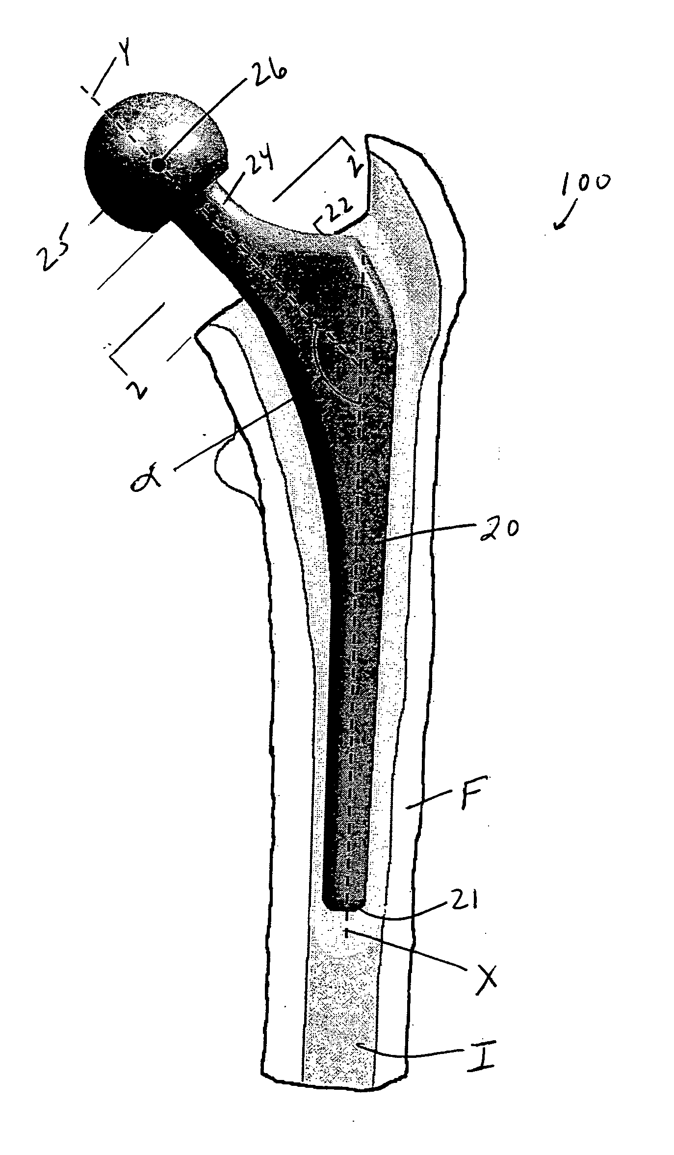
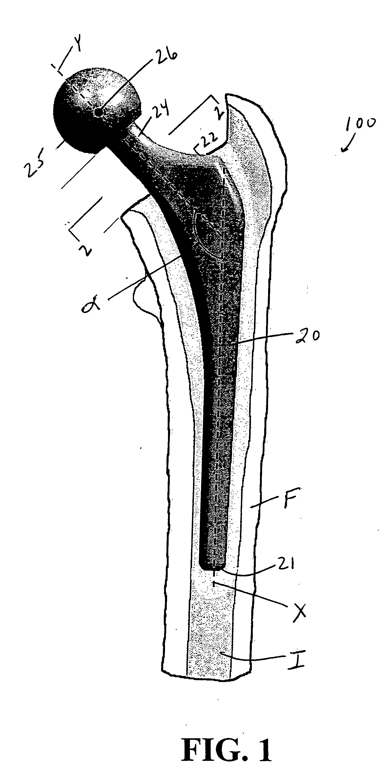
Femoral implant for hip arthroplasty
a technology of femoral implants and hip arthroplasty, which is applied in the field of femoral implants for hip arthroplasty, can solve the problems of dislocation of joints, rare practice results, and inability to allow patients to place legs in more extreme positions, so as to improve the balance between strength and motion of joints, reduce strength, and increase the range of motion of joints
- Summary
- Abstract
- Description
- Claims
- Application Information
AI Technical Summary
Benefits of technology
Problems solved by technology
Method used
Image

Examples
example 1
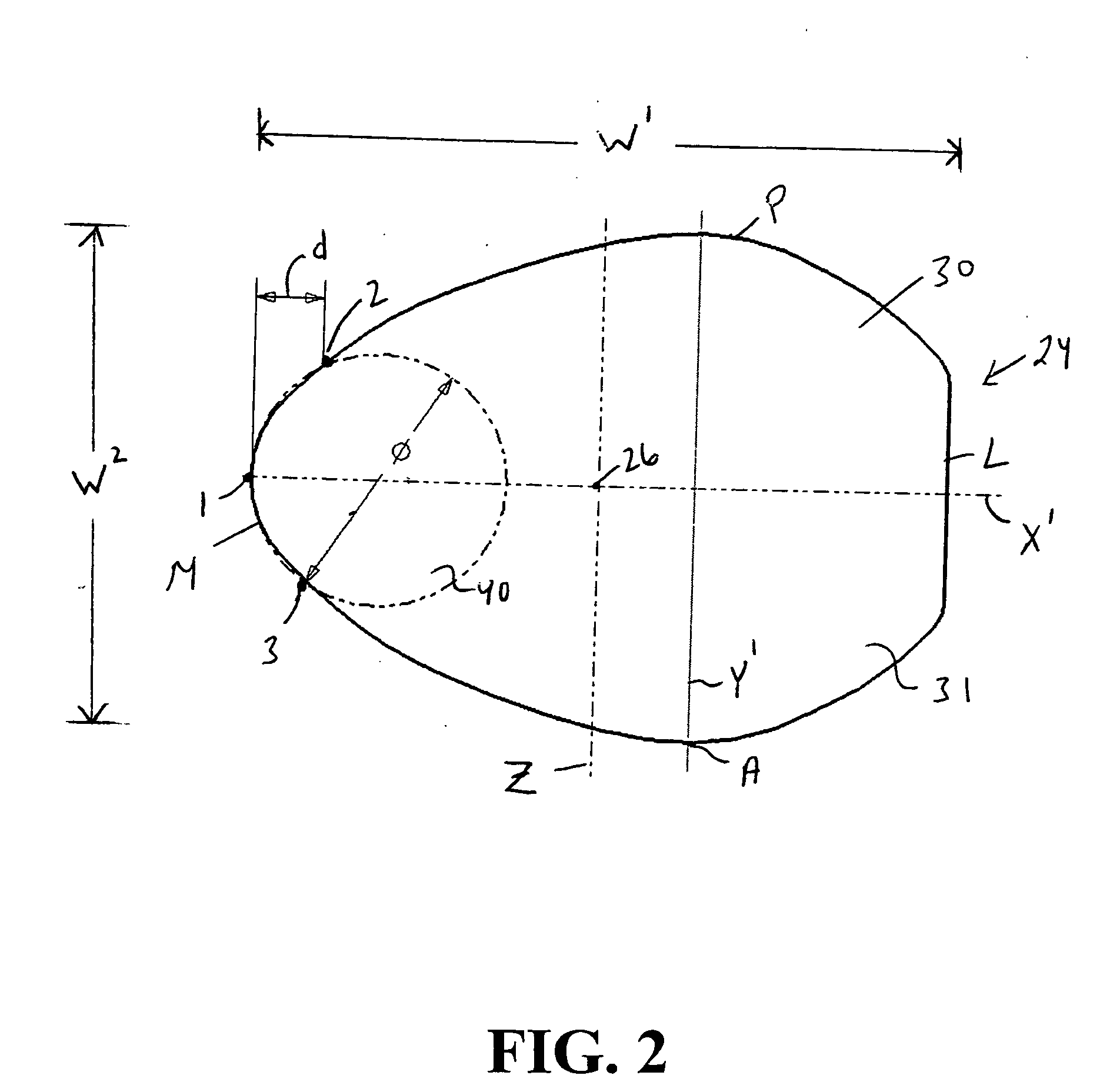
[0028] To make an accurate assessment of the range of motion provided by the present invention, CAD models were prepared of the preferred embodiment (illustrated in FIG. 7) and of conventional circular, rectangular, and trapezoidal designs. In each model, the cross-sectional geometry of the neck was held constant over a distance of 14 mm to 18 mm from the head center along the neck axis. Below this level, each neck was blended to a larger version of the cross-section, such that, at a level along the neck axis 35 mm below the head center, the medial-lateral and anterior-posterior width of the cross-section increased by 9 mm (FIG. 5).
[0029] The neck was placed in 15° of anteversion, 6° of adduction, and 5° of flexion relative to the longitudinal axis of the femur, and a load typically experienced by the femoral component during walking (Bergmann et al., 2001) was applied to the head center using finite element analysis software (Unigraphics NX). The dimensions of all four designs wer...
PUM
 Abstract
Description
Claims
Application Information