

Centrifuge for separating soot from the exhaust of an internal combustion engine
- Summary
- Abstract
- Description
- Claims
- Application Information
AI Technical Summary
Benefits of technology
Problems solved by technology
Method used
Image

Examples
Embodiment Construction
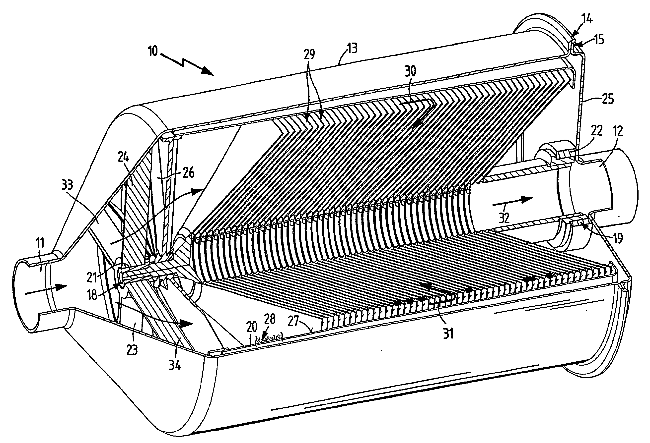
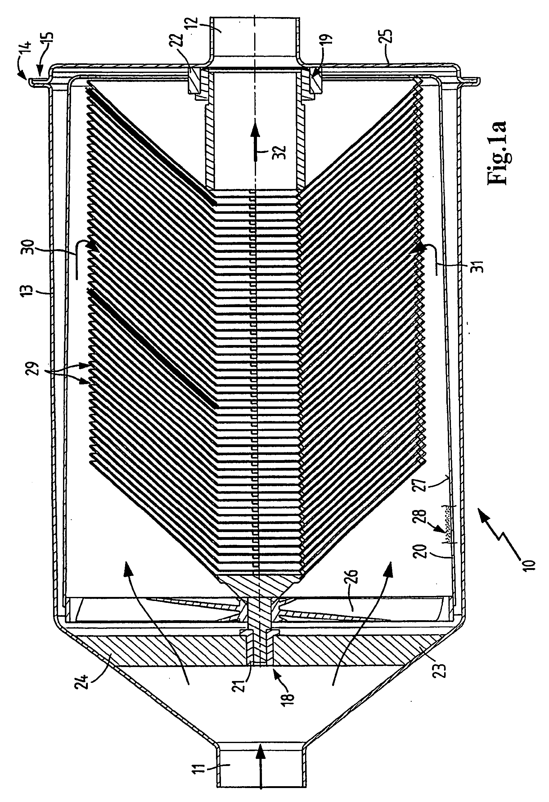
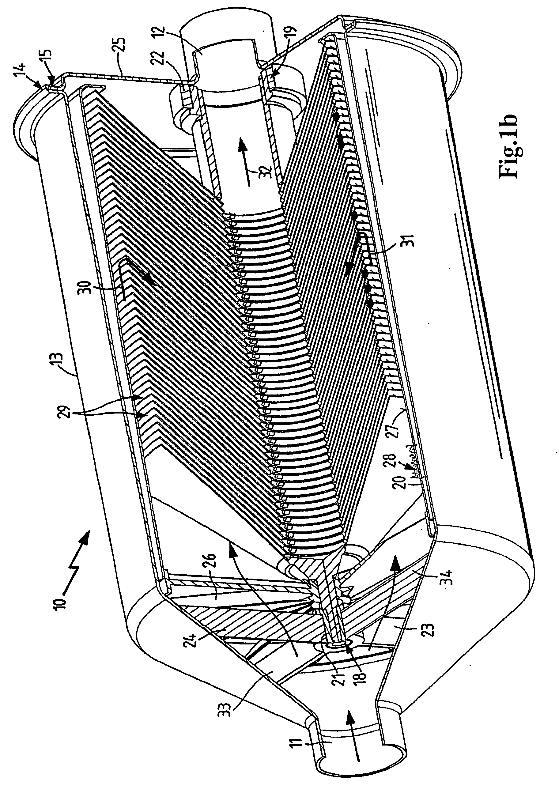
[0030]FIG. 1a shows a soot centrifuge 10 which is constructed as an in-line centrifuge and is arranged between a raw gas inlet pipe 11 and a clean gas outlet pipe 12. The centrifuge is located in a housing 13, which is directly connected to the raw gas inlet pipe and the clean gas outlet pipe and has a flange joint or connection 14, which is provided with a suitable closure system 15. Coaxial bearings 18 and 19 are provided adjacent both the raw gas inlet and also the clean gas outlet, which support the centrifuge rotor 20. The bearings 18 and 19 are advantageously a slide bearing with ceramic bushings 21, 22, which are resistant to high temperatures. The bearing 18 is attached to struts 23, 24. The bearing 19 is arranged on a housing cover 25, which joins outlet pipe 12.
[0031] The centrifuge has drive vanes 26 on the gas inlet side which cause the centrifuge rotor to rotate when exhaust gases flow in. The centrifuge itself is substantially a rotatable body having an inner housing ...
PUM
| Property | Measurement | Unit |
|---|---|---|
| Flow rate | aaaaa | aaaaa |
| Adhesion strength | aaaaa | aaaaa |
| Ignition point | aaaaa | aaaaa |
Abstract
Description
Claims
Application Information