Apparatus and method for making preforms in mold

a technology of apparatus and mold, applied in the direction of manufacturing tools, combs, buttons, etc., can solve the problems of composite material weak spots where the reinforcement is lacking, polymer materials tend to be much less strong than metal, and do not meet the strength requirements for metal replacement, etc., to achieve the effect of reducing cost and high strength structural preforms

Inactive Publication Date: 2005-07-28
BRUNSWICK CORPORATION
View PDF15 Cites 27 Cited by
  • Summary
  • Abstract
  • Description
  • Claims
  • Application Information

AI Technical Summary

Benefits of technology

[0014] An aspect of this invention provides an apparatus and a method in which a high strengt

Problems solved by technology

However, polymeric materials tend to be much lower in strength than metal.
Unless polymeric materials are reinforced in some manner, they often do not meet the strength requirements for metal replacement.
Otherwise, the composite will have weak spots where the reinforcement is lacking.
In addition, the individual fibers should be held in place to resist flowing with the molding resin as it enters the mold, which would disrupt the fiber distribution.
This means that the application of binder is at least a two-step process, which is not desirable from an economic standpoint.
Also, the use of solvents is encountered, which raises environmental, exposure and recovery issues.
Dealing with these issues potentially adds significantly to the expense of the process.
The procedure is also energy intensive, as the entire mat must be heated just to flash off solvent and cure the binder.
The curing step also makes the process take longer.
Use of the solvent-borne polymer binders is extremely messy.
There are also high maintenance costs associated with keeping the work area and the screen on which the mat is formed clean.
When a composite article is then prepared from a preform made in this way, the binder often interferes with the adhesion between the fibers and the continu

Method used


Image

  • Apparatus and method for making preforms in mold
  • Apparatus and method for making preforms in mold
  • Apparatus and method for making preforms in mold

Examples


Embodiment Construction

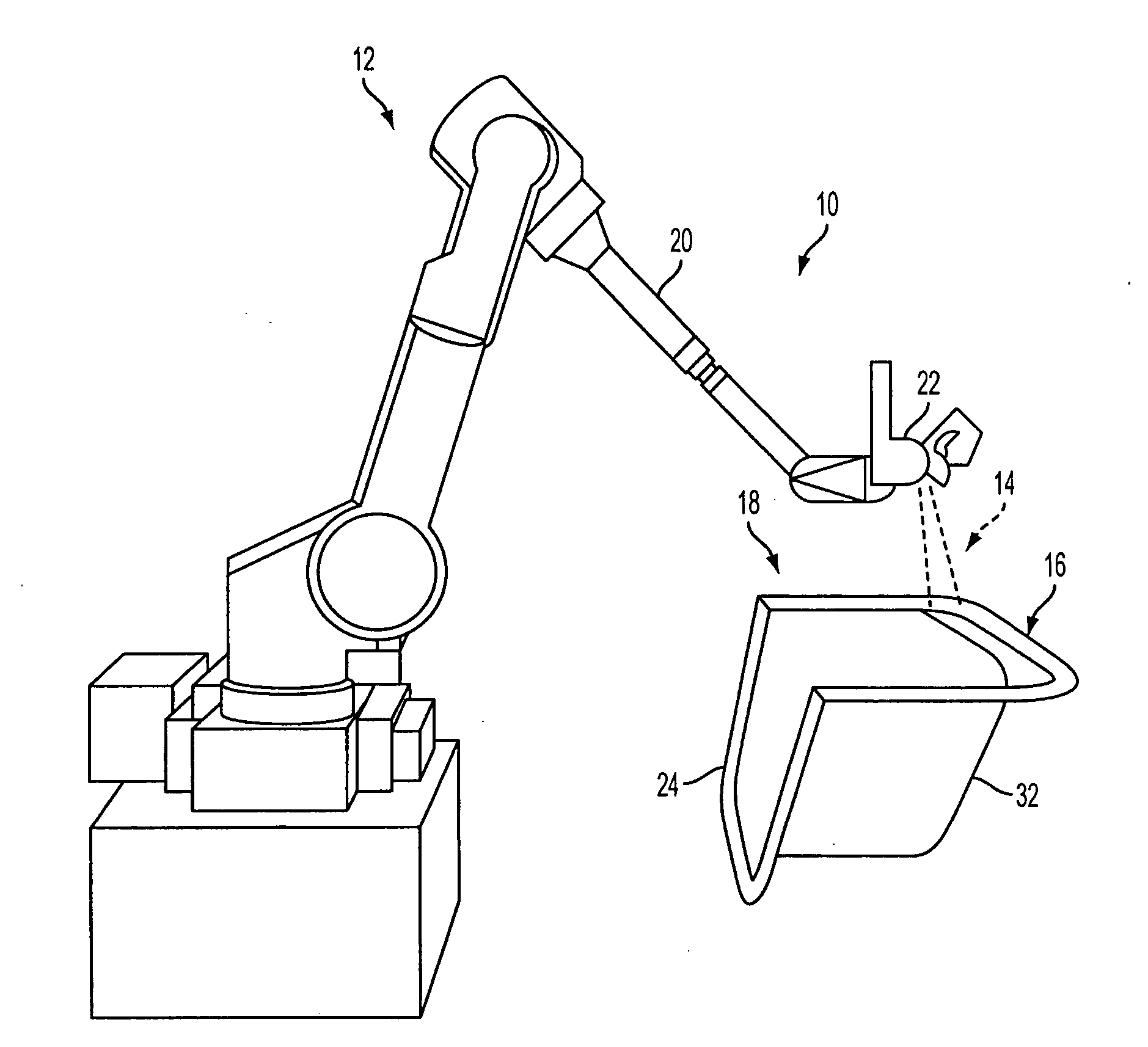
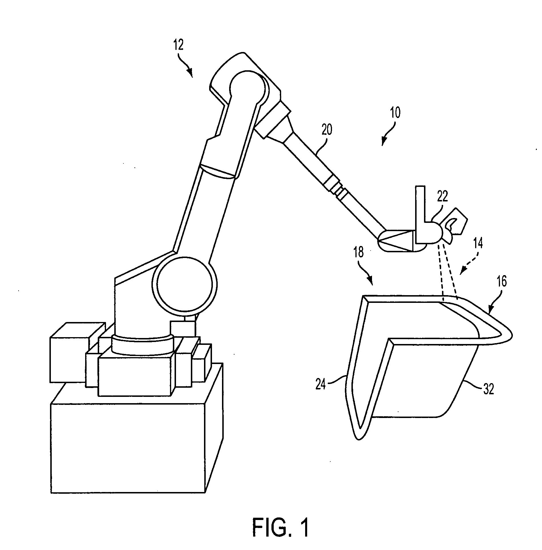
[0044] This invention is described below with reference to formation of a preform for use in the marine industry to construct fiberglass reinforced articles, such as a motor box for a boat, a hatch, deck, deck section or a boat hull. However, it is to be understood that this is an exemplary embodiment only and that the method can be applied in various applications in which high strength structural members are used. For example, a preform made in accordance with the disclosed embodiments of the invention could be used in the automotive, aircraft, or building industries or as a component of household goods, such as appliances. Further, although specific examples of materials are provided herein, any suitable material can be used.

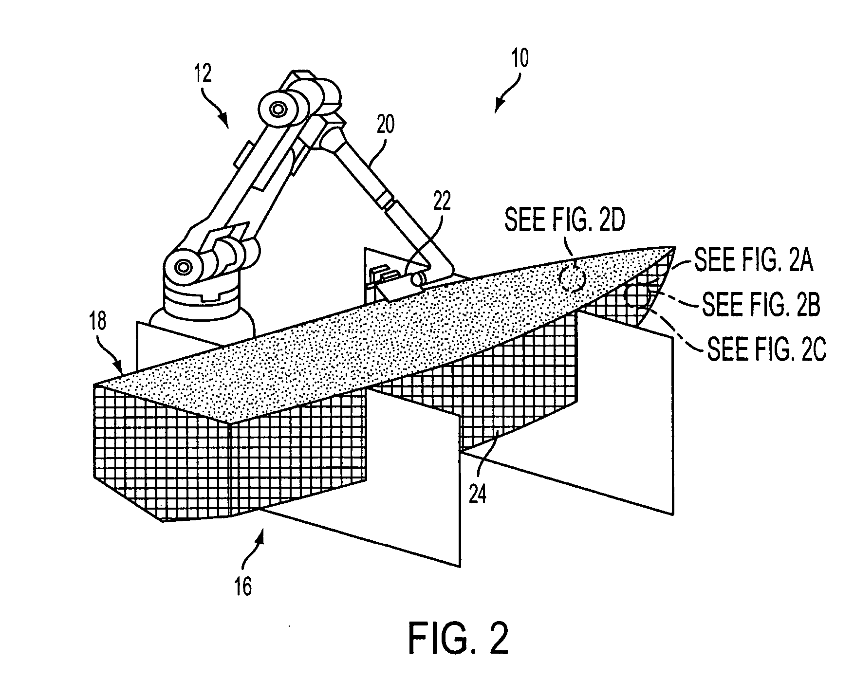
[0045] As seen in FIG. 1, a preform making assembly 10 used to practice a method in accordance with the invention includes a materials applicator 12 that applies the preform material mixture 14 to a support surface 16 to create preform 18. The term preform in...


PUM

PropertyMeasurementUnit
Pressureaaaaaaaaaa
Structureaaaaaaaaaa
Lengthaaaaaaaaaa

Abstract

Apparatus and a method of preparing fiber preforms disperses fibers and binder on a forming support surface such that the materials are conditioned and then applied to the surface where the composite material solidifies. Reinforcing material, such as fiber, is mixed with binder, such as thermoplastic or thermoset materials, so that the materials adhere. Then, the adhesive mixture is dispersed in a controlled pre-determined weight ratio on the support surface where the mixture sticks to the support surface, cools and solidifies. The deposited mixture can be an open mat having interstices between fibers. The deposited mixture can also be shaped further into a final desired shape before complete solidification. This method eliminates the need for solvents and their associated problems. The process does not require a vacuum or plenum system to hold the reinforcing material in place. The preform can be made in any shape, including sections or asymmetric configurations and remain in mold while being processed to a composite molded article.

Description

FIELD OF THE INVENTION [0001] This invention relates to an apparatus and a method of making a preform, particularly for use in composite molded articles, and also composite molded articles. The apparatus and the method especially relate to making a structural preform for use with polymeric materials. BACKGROUND OF THE INVENTION [0002] High strength polymeric materials are being increasingly used to replace traditional structural materials, such as metal, in many applications. The polymeric materials have the advantage of lower weight and are often less expensive and more durable than metals. However, polymeric materials tend to be much lower in strength than metal. Unless polymeric materials are reinforced in some manner, they often do not meet the strength requirements for metal replacement. [0003] Thus, polymeric composites have been developed to meet such strength requirements. These composites are characterized by having a continuous polymeric matrix within which is embedded a r...

Claims


Application Information

Patent Timeline
IPC IPC(8): B29B11/16B29CB29C31/00B29C70/30
CPCB29B11/16B29C70/305B29L2031/307B29K2223/0683B29K2105/06
Inventor LAMMERS, SCOTT A.SCHACHER, JONATHAN W.ANDERSON, CHRISTIAN S.OLSON, STEVE H.
Owner BRUNSWICK CORPORATION
Why Eureka
Try Eureka