
Airbag and method of producing an airbag

Inactive Publication Date: 2005-07-28
GLOBAL SAFETY TEXTILES
View PDF32 Cites 18 Cited by
  • Summary
  • Abstract
  • Description
  • Claims
  • Application Information

AI Technical Summary

Benefits of technology

[0006] The present invention is based on the objective of producing a low-cost air bag in avoiding or at least greatly diminishing the drawbacks of prior art, as well as proposing a method for producing such an air bag. This objective is firstly achieved by an air bag as it reads from claim 1. This air bag in accordance with the invention can now be fabricated significantly cheaper than air bags as known from prior art. By arranging the coatings on the surfaces of the fabric plies of the air bag facing outwards as suitable for forming the leakage resistance and strengthening of the air bag, the textile sheet fabric of the air bag can now be woven relatively loosely. Strengthening the air bag in this sense is meant as coating the air bag to achieve particularly high strength, leakage resistance and keying to the fabric. The fabric itself is responsible so-to-speak for forming the outer and inner structure of the air bag and its at least one chamber, i.e. it not primarily contributing towards leakage resistance and strength of the fabric as handled namely by the coating e.g. also in the form of a film. Now, because of this, the set of the fabric can be strongly redimensioned. Thus, for instance, the single-ply portions in a one-piece woven (OPW) can now be executed solid and tight in a (simpler) plain weave instead of a panama weave as hitherto. This greatly reduces the load on the fabric by shear forces at critical transitions from single-ply to two-ply portions with the same weave as achieved by the plain weave as proposed in this case, resulting in a drastic reduction in the risk of the coating becoming detached or damaged as arranged on the fabric, i.e. risk of leakage. By satisfying the required airtightness the air bag in accordance with the invention thus ensures the vital pressure withstanding duration.
[0007] Another advantage materializes from the smoother surface of the plain weave permitting better adhesion of the coating in further reducing the risk of leakage. Because of the lower set and the resulting higher output of the weaving machine, the air bag fabric and one-piece wovens (OPW) in the shop and finishing can now be produced and worked to advantage substantially cheaper. Due to the fewer shed changes as well as due to the lesser attrition of the threads against each other the load on the yarn material is significantly reduced, resulting in a drastic reduction in impairments (capillary damage, fluffing, conglomerations, thread breakage and the like) in thus immensely enhancing product quality. Since this involves the weaving machine being down far less because of yarn impairment, efficiency is boosted substantially.
[0010] It is known to coat textile sheet fabrics with fluids, films, film-like materials or laminates and the like, serving e.g. to enhance the resistance to ageing and / or leakage and / or to reduce permeability and / or friction, etc. When such textile sheet fabrics are overtaxed mechanically, hydraulically or pneumatically the key between the textile sheet fabric and the coating is disrupted which may even result in a total malfunction of the textile sheet fabric.

Problems solved by technology

To attain the needed strength and airtightness the fabric must be fabricated suitably high set which because of the high material consumption results in fabrication being expensive.
Since in many cases the air bag fabric made in this way still fails to exhibit an adequate leakage resistance, additional thin films are added in an expensive process with the sole objective of sealing the fine pores of the fabric to achieve the necessary leakage resistance.
Air bags fabricated as such are, on the one hand, because of the weaving method very expensive.
On the other, the expense of the air bags is further increased by the complicated coating process.
Because of its high density, finishing such a fabric is a slow and thus cost-intensive process.
Known air bag fabrics have the further drawback that because of the dense set and involving the slower weaving process the load on the yarn is correspondingly higher.
Thus, during the transition in weaving the threads from the upper into the lower position and vice-versa the threads rub against each other all the more often and intensified because of the dense set, to the detriment of the quality in weaving (capillary damage, fluffing, conglomerations, thread breakage and the like) resulting in a high degree of spoilage.
Moreover, thread damage in weaving results in many cases in downtime of the weaving machine, also due to machine speeds needing to be increasingly higher causing a serious loss of efficiency which in turn further adds to the already high costs of production.
Another drawback of the air bags as discussed is that due to the high set and because of the correspondingly high fabric thickness of the air bag fabric a certain packing volume of the finished air bag needs to be assured in the folded condition.
Because of the high set the fabric or air bag becomes stiffer, further adversely influencing working the fabric.
As a rule the surfaces of e.g. of woven, knitted or netted textile sheet fabrics as representing the aforementioned surfaces, for example, are not smooth in structure but “bumpy”, resulting in no continuous flat contact surface being available for a coating, e.g. in the form of a film.
When such textile sheet fabrics are overtaxed mechanically, hydraulically or pneumatically the key between the textile sheet fabric and the coating is disrupted which may even result in a total malfunction of the textile sheet fabric.

Method used


Image

  • Airbag and method of producing an airbag
  • Airbag and method of producing an airbag

Examples


Embodiment Construction

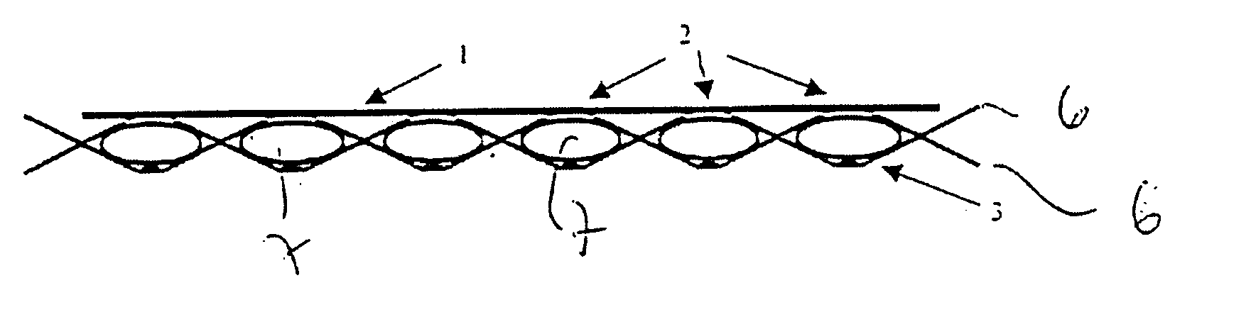
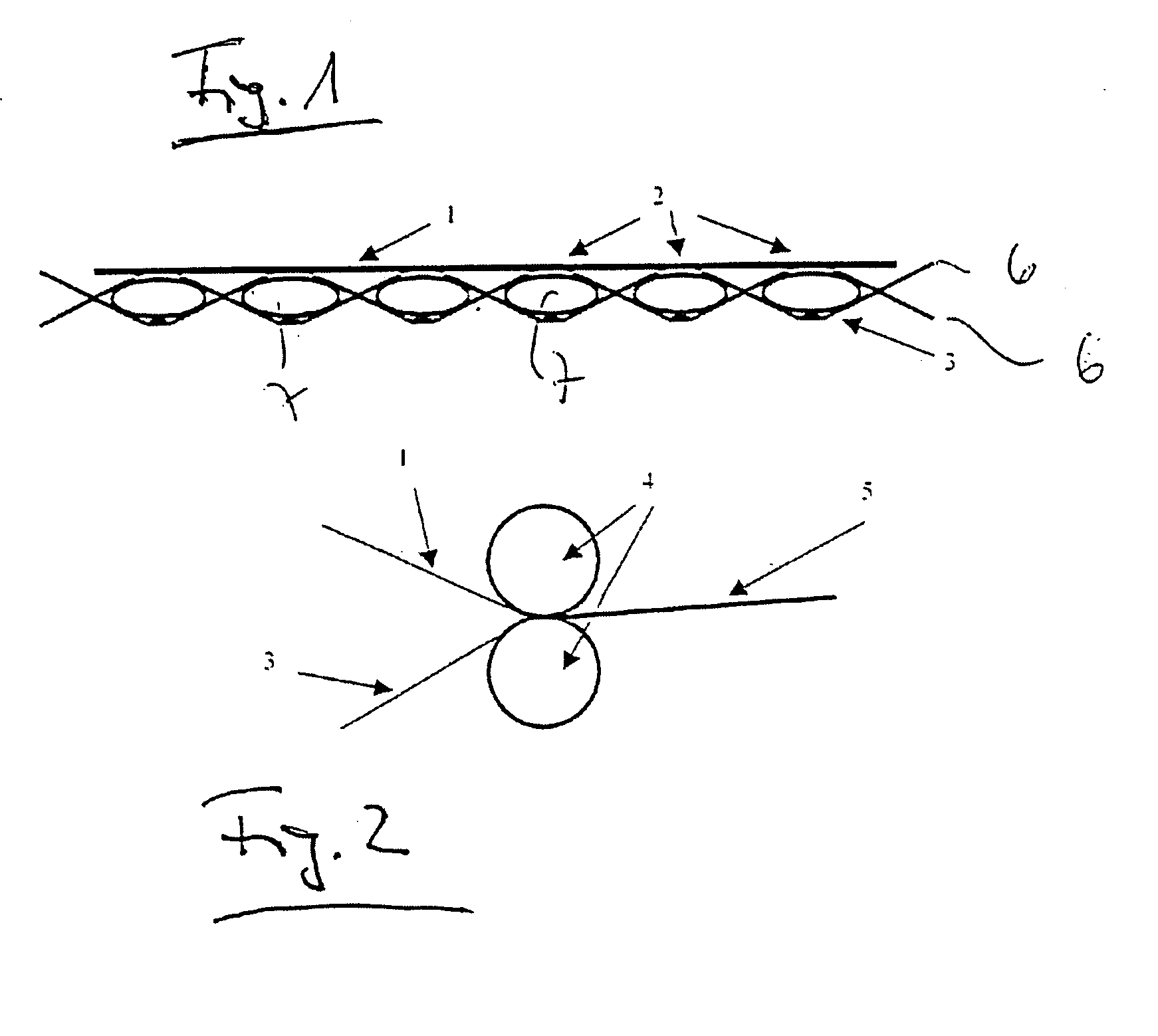
[0016] Referring now to FIG. 1 there is illustrated a fabric including weft threads 6 and (not shown true to scale) warp threads 7. Indicated are so-called keying points 2 to which a film 1 optimized as to adhesion, resistance to leakage and strength is applied to a fabric 3 formed by weft and warp threads 6 and 7 respectively. Due to the fabric 3 being compressed by a pair of nip rollers 4 as shown in FIG. 2 the warp threads 7 are squeezed together so that they become elliptical cross-sectionally. Likewise evident from the arrangement as shown in FIG. 1 simply diagrammatical is how the keying “points”2 become flattened between film / coating and fabric.

[0017] Referring now to FIG. 2 there is illustrated a pair of nip rollers 4 between which the film 1 as cited above and the backing fabric 3 thinned in the thread densities is guided and keyed. The resulting key of film / coating and fabric is achievable, chemically, thermally or mechanically, resulting in so-to-speak a textile-strength...


PUM

PropertyMeasurementUnit
Pressureaaaaaaaaaa
Surface structureaaaaaaaaaa

Abstract

The invention relates to a two-ply airbag consisting of a textile surface structure, said plies lying opposite one another and enclosing at least one chamber that can be filled with gas. The piles have surfaces that face outwards. The airbag is characterized in that coatings, which are suitable for sealing and reinforcing the airbag, are applied to said surfaces.

Description

CROSS-REFERENCE TO RELATED APPLICATIONS [0001] This application is a Continuation of PCT Application No. PCT / EP03 / 05697 filed on May 30, 2003, which claims priority to German Application No. DE 102 24 771.4-42, filed on Jun. 4, 2002; both of which are incorporated by reference herein.BACKGROUND AND SUMMARY OF THE INVENTION [0002] The invention relates to an air bag comprising two plies of a textile sheet fabric, the plies facing each other and enclosing at least one chamber that can be filled with gas, the plies having surfaces facing outwards, the invention also relating to a method of producing such an air bag. [0003] Air bag fabrics are in use whose technical properties are dictated by the dense structure of the fabric. To attain the needed strength and airtightness the fabric must be fabricated suitably high set which because of the high material consumption results in fabrication being expensive. Fully fabricated or one-piece woven (OPW) air bags need to satisfy the crash withs...

Claims


Application Information

Patent Timeline
IPC IPC(8): B32B5/26B32B38/00B60R21/16B60R21/235D06N3/00
CPCB32B5/26B32B38/00B32B38/0008B32B2038/0024D06N3/0002B32B2310/14B60R21/235B60R2021/23514B32B2305/18B32B37/0053B32B5/08B32B5/24B32B5/024B32B5/022
Inventor BERGER, JOHANNSAINT-DENIS, HOLGERHUBER, NORBERTRUSCHULTE, JORG
Owner GLOBAL SAFETY TEXTILES
Learn More