
Transceiver apparatus and transceiving method

a transceiver and transmitter technology, applied in the field of transceiver apparatus and to transceive broadcasting, can solve the problems of increasing susceptibility to effects and loss of orthogonality, and achieve the effects of accurate detection, accurate carrier-frequency synchronization, and accurate detection

Inactive Publication Date: 2005-07-28
FUJITSU LTD
View PDF6 Cites 142 Cited by
  • Summary
  • Abstract
  • Description
  • Claims
  • Application Information

AI Technical Summary

Benefits of technology

The present invention aims to accurately detect the timing of a synchronization channel (SCH) frame, even in cases where carrier frequency synchronization is unsatisfactory and residual carrier-frequency error is not negligible. It also aims to achieve highly precise carrier-frequency synchronization and residual carrier-frequency offset compensation, even in the presence of interference from other cells. Additionally, it aims to perform channel estimation and CSSC identification without interference from a DPCH. The invention achieves these technical effects by providing a method for exclusive transmission of the SCH signal sequence on a separate subcarrier, and differential encoding and processing of the signal sequence to improve frame timing detection and phase error correction. Furthermore, the invention utilizes the correlation between the SCH signal sequence and the cell-identifying scramble codes to improve channel estimation and compensation accuracy.

Problems solved by technology

If symbol length is increased, however, a drawback is that in the event that a carrier frequency offset occurs, there is increased susceptibility to the effects thereof.
The frequency deviation Δf leads to interference between neighboring carriers and causes loss of orthogonality.

Method used


Image

  • Transceiver apparatus and transceiving method
  • Transceiver apparatus and transceiving method
  • Transceiver apparatus and transceiving method

Examples


first embodiment

[0150]FIG. 19 is a block diagram of a first embodiment of AFC control. In a first stage, an AFC unit 66, in a manner similar to that of the example of the prior art (see FIGS. 33 to 35), performs peak detection based upon guard-interval correlation, detects phase error of the correlation value at the peak timing and controls the oscillation frequency of a VCO-implemented local oscillator 61 via a switch 67 so as to reduce the phase error.

[0151] Next, SCH frame timing, FFT window timing and the symbol interval M of differential decoding are decided by the control of FIG. 17. The FFT calculation unit 71 thenceforth performs the FFT operation at this FFT window timing, and the differential decoders 721 to 72NSCH perform differential decoding over a plurality of symbol intervals with regard to subcarrier signals to which SCH has been assigned, namely the operation of Equation (16). The adder 73 combines the differentially decoded results and outputs the SCH combined signal.

[0152] On t...

second embodiment

[0154]FIG. 20 is a block diagram of a second embodiment of AFC control. This illustrates an arrangement for a case where the combining of subcarrier signals to which SCH has been assigned has been performed in accordance with the CMA algorithm. Control of carrier frequency synchronization in the latter stage is an operation similar to that of FIG. 19.

[0155] In a first stage, an AFC unit 66, in a manner similar to that of the example of the prior art (see FIGS. 33 to 35), performs peak detection based upon guard-interval correlation, detects phase error of the correlation value at the peak timing and controls the oscillation frequency of the VCO-implemented local oscillator 61 via the switch 67 so as to reduce the phase error.

[0156] Next, SCH frame timing, FFT window timing and the symbol interval M of differential decoding are decided by the control of FIG. 18. The FFT calculation unit 71 thenceforth performs the FFT operation at this FFT window timing, and the CMA combiner 77 out...


PUM


Abstract

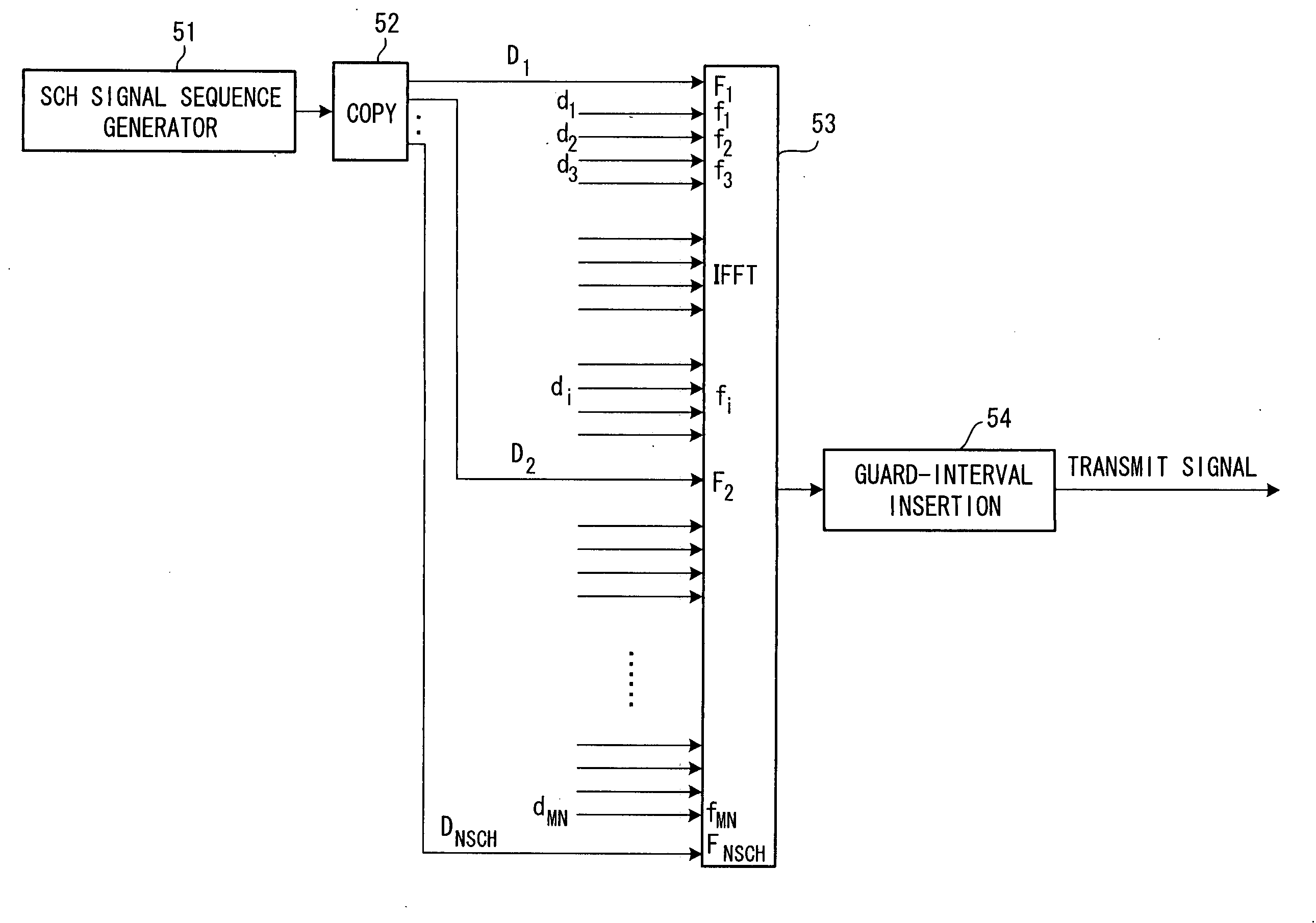
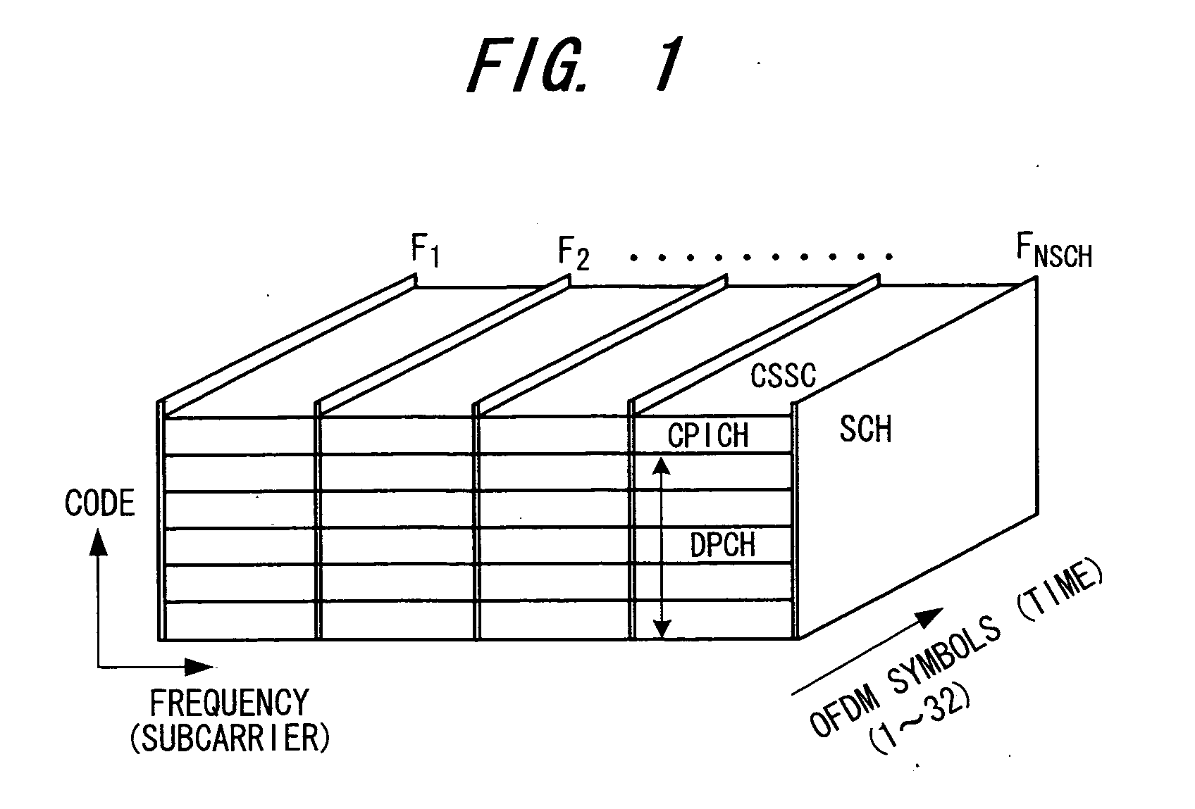
In a transmitting method for transmitting a transmit signal sequence by a number of subcarriers, a plurality of subcarriers F1, F2, . . . FNSCH exclusively for a synchronization channel are provided, a signal sequence of synchronization channel SCH is transmitted by the plurality of exclusive subcarriers, and a common pilot CPICH or dedicated signal DPCH is transmitted on the other subcarriers. In this case, the signal sequence of the synchronization channel is subjected to differential encoding processing and the differentially encoded signal sequence is transmitted by the exclusive subcarriers.

Description

BACKGROUND OF THE INVENTION [0001] This invention relates to a transceiver apparatus and to transceive broadcasting. More particularly, the invention relates to a transceiver apparatus and transceive broadcasting for transmitting a transmit signal sequence using a number of subcarriers. [0002] Multicarrier modulation schemes have become the focus of attention as next-generation mobile communication schemes. Using multicarrier modulation not only makes it possible to implement wideband, high-speed data transmission but also enables the effects of frequency-selective fading to be mitigated by narrowing the band of each subcarrier. Further, using OFDM (Orthogonal Frequency Division Multiplexing) not only makes it possible to raise the efficiency of frequency utilization but also enables the effects of inter-symbol interference to be eliminated by providing a guard interval for every OFDM symbol. [0003] In recent years, there has been extensive research in multicarrier CDMA schemes (MD-...

Claims


Application Information

Patent Timeline
Patent Type & Authority Applications(United States)
IPC IPC(8): H04B1/707H04B1/7083H04B1/7087H04J11/00H04K1/10H04L5/02H04L27/26
CPCH04B1/7083H04L5/0007H04L5/0021H04L5/0048H04L25/022H04L25/0226H04L27/2662H04L25/03866H04L27/2613H04L27/2656H04L27/2657H04L27/266H04L25/023H04L27/26134
Inventor FUJII, MASAAKI
Owner FUJITSU LTD
Learn More