Image processing apparatus with preheating control

a technology of preheating control and image processing, applied in the direction of electrographic process apparatus, instruments, optics, etc., can solve the problems of hot offset, irregular gloss, and possible inadequate fusing, and achieve the effect of stable fusing temperatur

Active Publication Date: 2005-07-28
OKI ELECTRIC IND CO LTD
View PDF3 Cites 12 Cited by
  • Summary
  • Abstract
  • Description
  • Claims
  • Application Information

AI Technical Summary

Benefits of technology

[0008] An object of the present invention is to provide an image forming apparatus with a fuser that can maintain a stable fusing temperature throughout the fusing process, including the initial part of the fusing process.

Problems solved by technology

The low temperature is therefore not corrected immediately, causing a so-called cold offset that can produce gloss irregularities and possible inadequate fusing.
This problem is aggravated by the relatively low fusing temperatures that are now used to reduce power consumption and increase printing speed in much image forming apparatus.
The cold offset could be mitigated by temporarily raising the turn-on threshold before each sheet of printing media entered the fuser, but this scheme would invite the opposite problem: a hot offset could occur.

Method used


Image

  • Image processing apparatus with preheating control
  • Image processing apparatus with preheating control
  • Image processing apparatus with preheating control

Examples


first embodiment

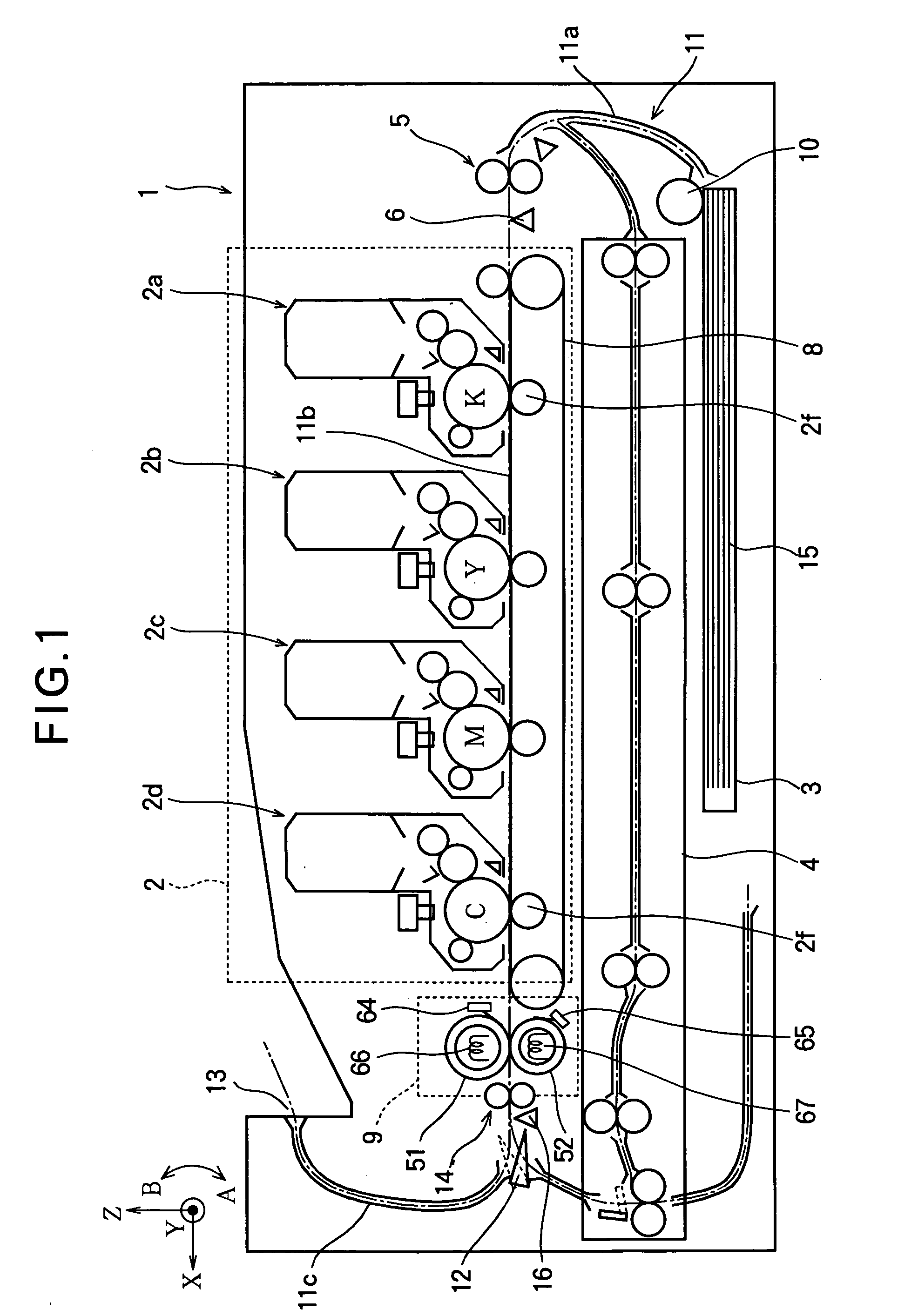
[0025] Referring to FIG. 1, the image processing apparatus 1 in the first embodiment is a two-sided color printer with a printing process unit 2 having black (K), yellow (Y), magenta (M), and cyan (C) developing units 2a, 2b, 2c, 2d and corresponding transfer rollers 2f. Printing media can be fed into the printing process unit 2 from either a cassette 3 or a double-sided paper feeding unit 4. Before entering the printing process unit 2, the printing media are aligned by a registration roller 5 and detected by a printing media sensor 6. Within the printing process unit 2, the printing media are transported by a transport belt 8, which carries the printing media between a photosensitive drum in each developing unit 2a, 2b, 2c, 2d and the corresponding transfer roller 2f. The printing process unit 2 functions as the image forming unit by forming black, yellow, magenta, and cyan toner images on the photosensitive drums in the developing units 2a, 2b, 2c, 2d and transferring the toner im...

second embodiment

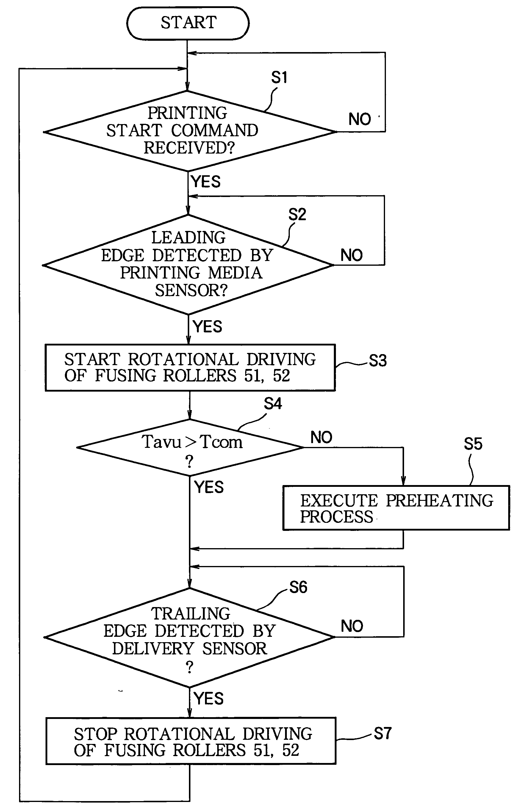
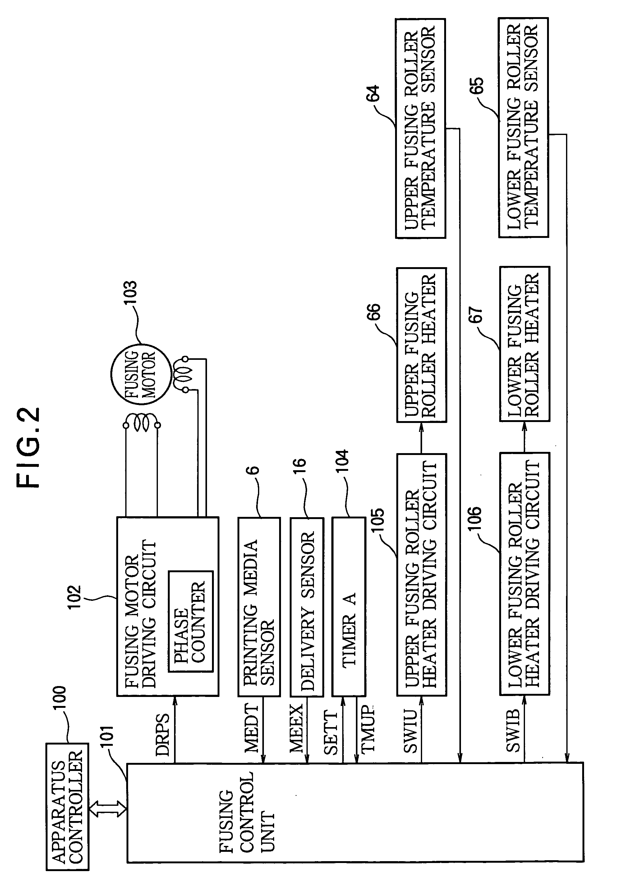
[0051] The second embodiment is a color printer having the mechanical configuration shown in FIG. 1 and the control system shown in FIG. 6. The second embodiment differs from the first embodiment in the addition of a second timer B 114 to the control system. The fusing control unit 101 in FIG. 6 uses timer B to decide whether or not to execute the preheating process, instead of making this decision by comparing the fusing roller surface temperatures with a threshold temperature as in the first embodiment.

[0052] Like timer A 104, timer B 114 receives a set-time signal SETT from the fusing control unit 101, measures a corresponding interval of time, and returns a time-up signal TMUP to the fusing control unit 101 at the end of the interval. The fusing control unit 101 uses timer B to measure a post-fusing interval Td starting from the time at which the delivery sensor 16 recognizes the trailing edge of the printing paper 15. The fusing control unit 101 executes the preheating process...

third embodiment

[0069] The third embodiment is a color printer having the mechanical configuration shown in FIG. 1 and the control system shown in FIG. 9. The third embodiment differs from the first embodiment in the addition of an average heater-on time calculator 107 to the control system. The fusing control unit 101 in FIG. 9 uses the average heater-on time calculator 107 to decide whether or not to execute the preheating process, instead of making this decision by comparing the fusing roller surface temperatures with a temperature threshold.

[0070] The average heater-on time calculator 107 receives the switching signals SWIU and SWIB output from the fusing control unit 101 to the roller heater driving circuits. At regular averaging intervals, the average heater-on time calculator 107 calculates the average percentage of time during which each of the roller heaters has been turned on during the preceding averaging interval. The calculated average heater-on times of the upper and lower fusing rol...


PUM


Abstract

An image forming apparatus has a fuser that fuses a toner image onto a printing medium by heat and pressure. The fuser temperature is sensed, and a heater in the fuser is controlled to keep the fuser at a constant temperature appropriate for fusing. In addition to constant-temperature control, the fuser is preheated to prevent an anticipated drop in its temperature when the printing medium encounters the fuser. The preheating process is carried out selectively and is omitted when not required, as determined from, for example, the temperature of the fuser when the printing medium enters the image forming unit of the image forming apparatus, the interval between the transport of different sheets of the printing medium, or the average amount of heat generated by the heater during a preceding interval.

Description

BACKGROUND OF THE INVENTION [0001] 1. Field of the Invention [0002] The present invention relates to an image forming apparatus having a fuser that thermally fuses a recording agent onto printing media, more particularly to the temperature control of the fuser. [0003] 2. Description of the Related Art [0004] Japanese Unexamined Patent Application Publication No. H7-248701 describes a method of controlling the temperature of this type of fuser by using a temperature sensor to sense the temperature of the fuser and a comparator to compare the sensed temperature with a threshold. A heater in the fuser is turned on and off according to the comparison result, using different turn-on and turn-off thresholds. [0005] When this method is practiced, the temperature sensor generally senses the surface temperature of a fusing roller. This temperature tends to drop when the surface of the printing medium makes contact with the fusing roller. Although the temperature sensor may detect the drop an...

Claims


Application Information

Patent Timeline
Patent Type & Authority Applications(United States)
IPC IPC(8): G03G21/00G03G15/20
CPCG03G15/657G03G15/2046G03G2215/20G03G2215/00721
Inventor WATABE, TOMONORI
Owner OKI ELECTRIC IND CO LTD
Why Eureka
Try Eureka