Low level ultraviolet disinfecting system

a disinfecting system and ultraviolet light technology, applied in space heating and ventilation, lighting and heating apparatus, heating types, etc., can solve the problems of uv energy, certain materials may degrade rapidly, and certain materials may be exposed to uv energy, so as to reduce the level of energy and reduce the risk of microbial growth, the effect of safe human exposure levels

Inactive Publication Date: 2005-07-28
ULTRAVIOLET DEVICES
View PDF12 Cites 21 Cited by
  • Summary
  • Abstract
  • Description
  • Claims
  • Application Information

AI Technical Summary

Benefits of technology

[0011] In accordance with another aspect of the invention, a disinfecting method comprises the steps of providing at least one light source having output suitable for use as a germicidal agent, limiting the output of the light source to levels adequate for microbial growth control, and attenuating the limited output by fluid-conveying equipment components disposed within the output range of the light source. The light source is operatively housed in fluid-conveying equipment for fluid disinfection. The attenuated output provides safe human exposure levels in the vicinity of fluid intake and exhaust portions of the fluid-conveying equipment.
[0012] In accordance with yet another aspect of the invention, a disinfecting system comprises an electromagnetic energy source, and a power supply designed to supply current to the electromagnetic energy source such that a lower level of energy than rated by a standard energy source is emitted, by using a near rated cathode current to maintain lamp life, and a percentage of rated lamp current, within HVAC equipment. The energy output is sufficiently controlled to reduce microbial growth and energy output is reduced to prohibit unsafe levels and reduce degradation of HVAC system components.
[0013] In accordance with still another aspect of the invention, a method of disinfecting air, surfaces, fluids and other things utilizing a lower than standard or rated level of electromagnetic energy comprises the steps of providing an electromagnetic energy source, electrically coupling a power supply to the electromagnetic energy source, and powering the electromagnetic energy source with a percentage of rated lamp current, and near rated cathode current to reduce emitted energy and to enhance the life of the electromagnetic energy source.
[0014] In accordance with a further aspect of the invention, a disinfecting system for disinfecting air, surfaces, fluids and other objects comprises an electromagnetic energy source, and a power supply electrically coupled to the electromagnetic energy source. The electromagnetic energy is emitted at lower than rated levels by supplying the electromagnetic energy source with near rated cathode current and a percentage of rated lamp current. The emitted energy is sufficiently controlled to reduce microbial growth and otherwise disinfect, and the emitted energy is reduced to prohibit unsafe levels of emitted energy and to reduce degradation of system components.

Problems solved by technology

While the use of UV energy has proven beneficial, there are known risks and negative aspects of its use.
Certain materials may degrade rapidly from UV exposure.
UV energy, particularly in the germicidal range (approximately 254 nanometers) may be harmful to the skin and eyes of humans and animals.
In these types of applications, excessively high levels of UV may damage components and may require shielding of certain materials and components.
Another problem may arise when UV lamps are operated at lower levels than the current at which UV lamps are rated.
This situation may cause the lamp to fail prematurely, which may lead to increased operating costs of the system.
In many small HVAC systems, there is very limited space for mounting the UV lamp.
It may be extremely difficult to fit the UV lamp within an existing HVAC installation.

Method used


Image

  • Low level ultraviolet disinfecting system
  • Low level ultraviolet disinfecting system
  • Low level ultraviolet disinfecting system

Examples


Embodiment Construction

[0024] The detailed description set forth below in connection with the appended drawings is intended as a description of exemplary embodiments and is not intended to represent the only forms in which the exemplary embodiments may be constructed and / or utilized. The description sets forth the functions and the sequence of steps for constructing and operating the exemplary embodiments in connection with the illustrated embodiments. However, it is to be understood that the same or equivalent functions and sequences may be accomplished by different embodiments that are also intended to be encompassed within the spirit and scope of the invention.

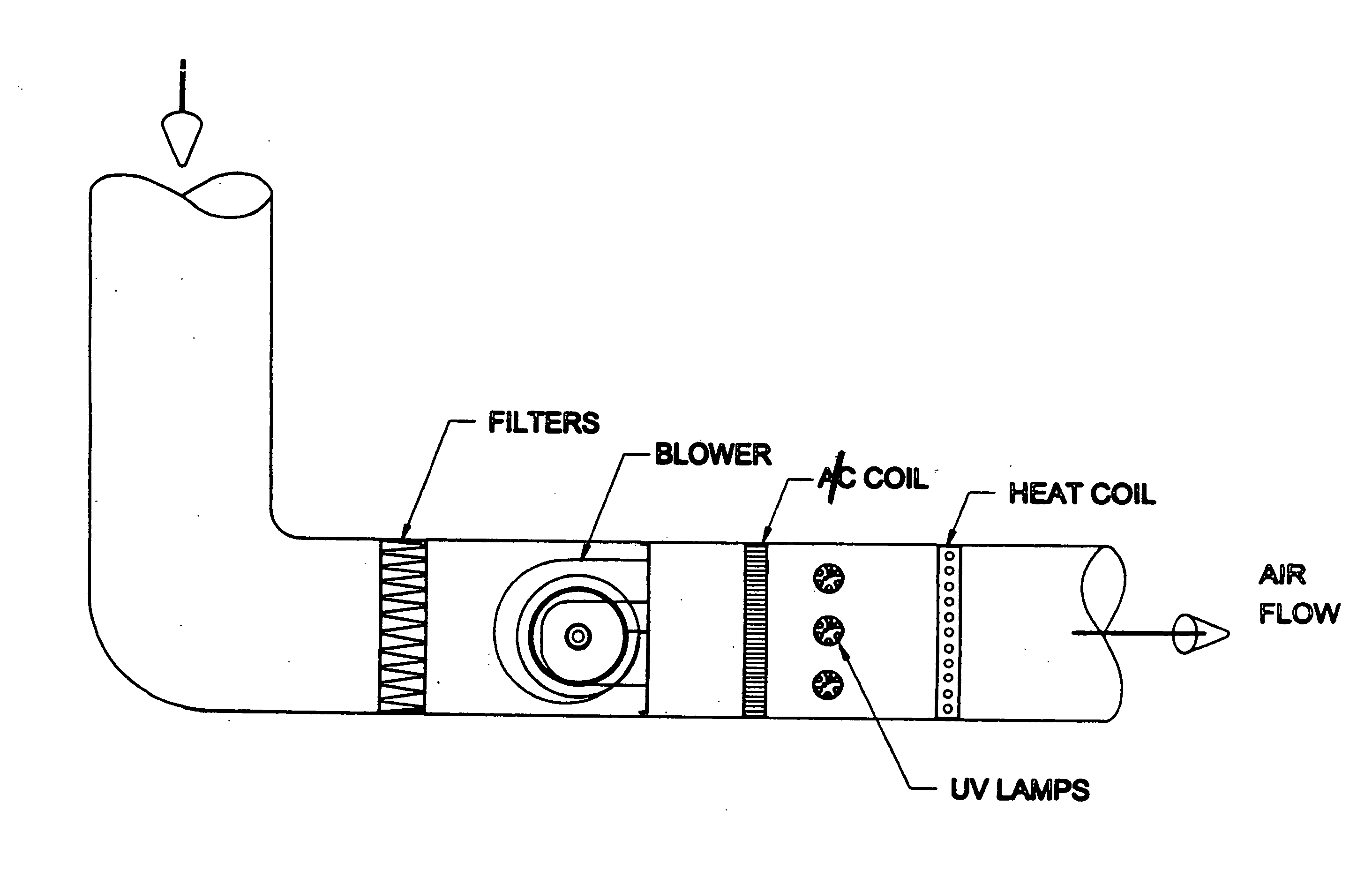
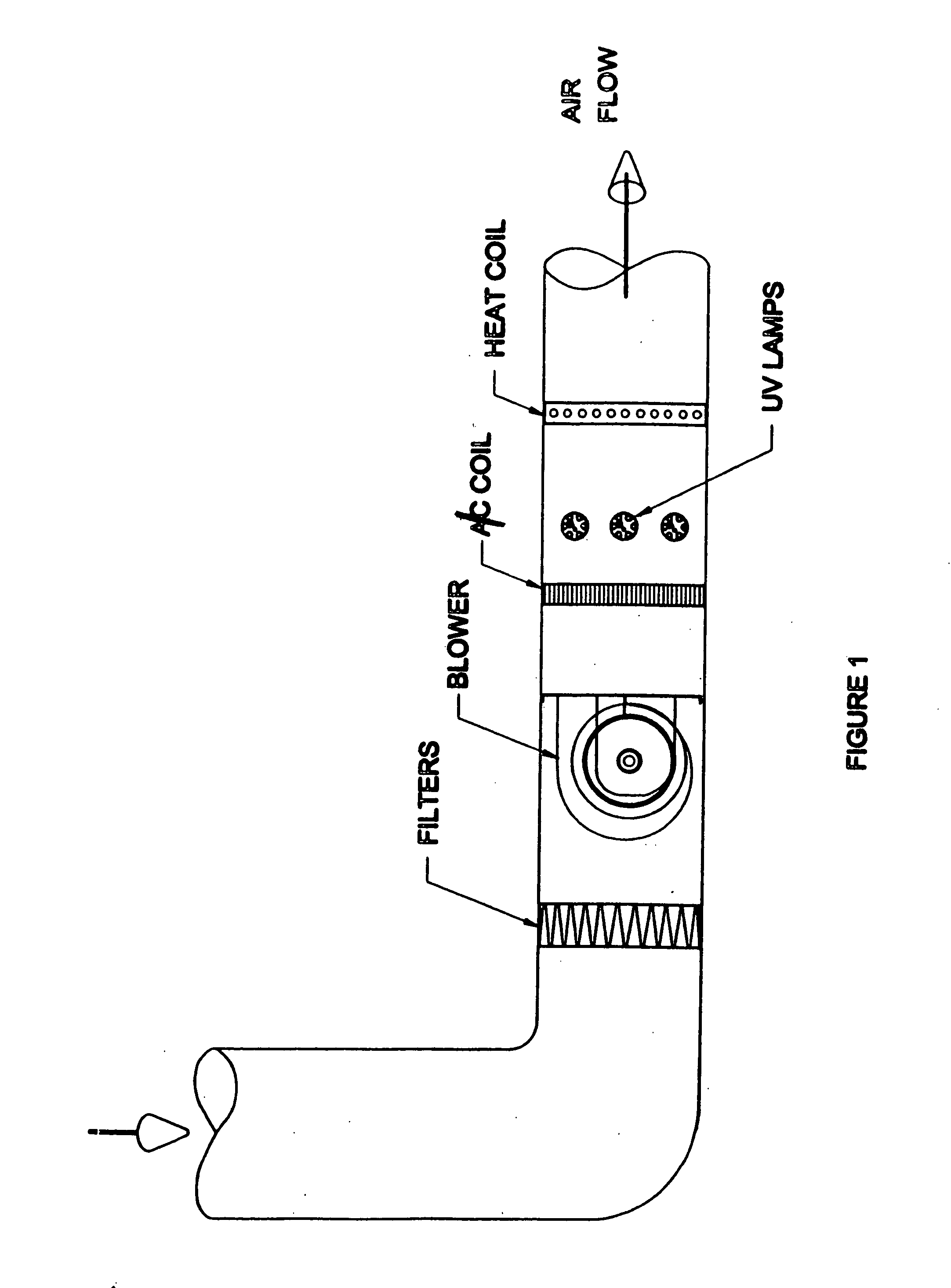
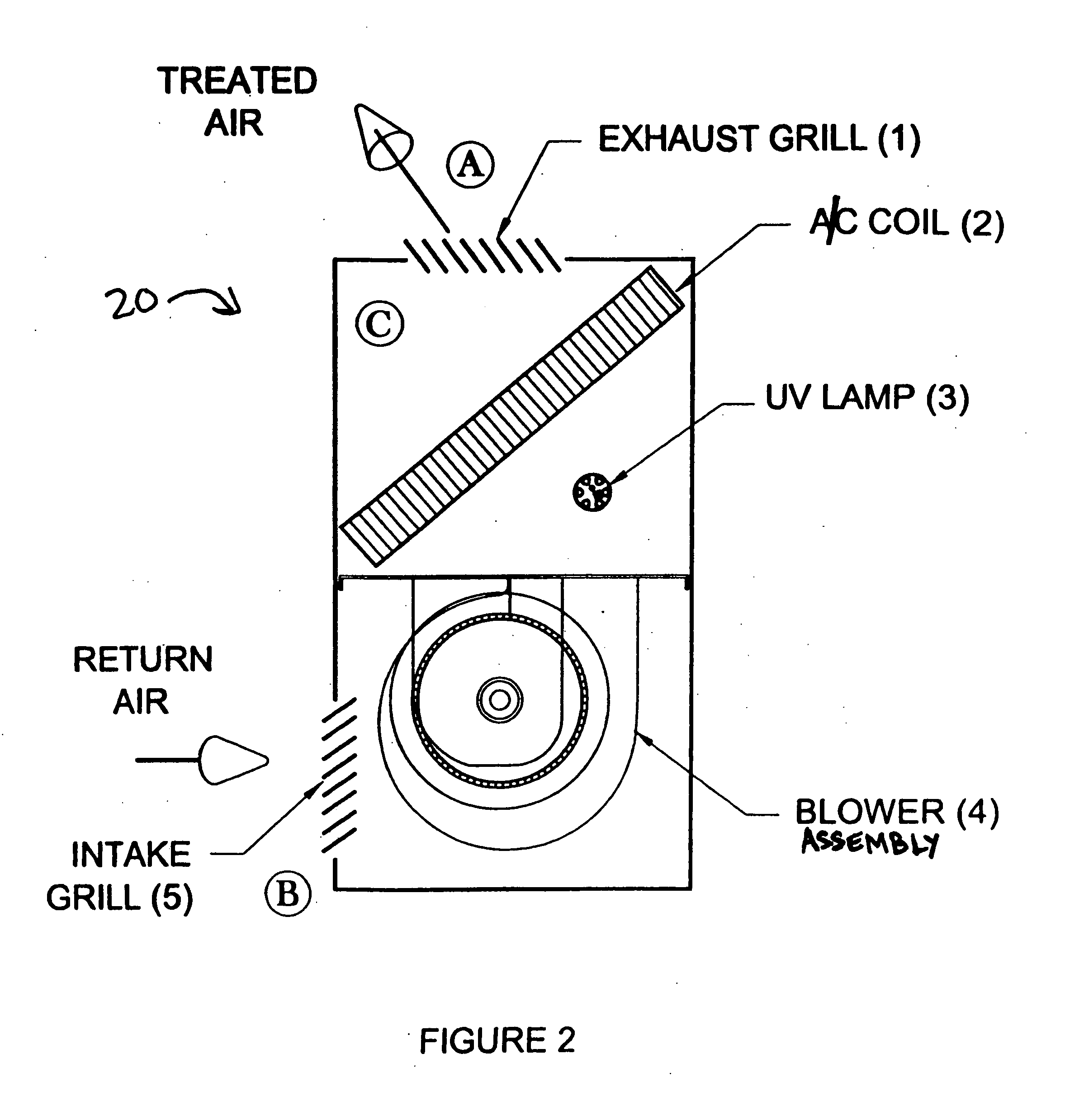
[0025] Some embodiments of the invention will be described in detail with reference to the related drawings of FIGS. 1-5. Additional embodiments, features and / or advantages of the invention will become apparent from the ensuing description or may be learned by practicing the invention. In the figures, the drawings are not to scale with like nume...


PUM

PropertyMeasurementUnit
UVC transmittanceaaaaaaaaaa
transmittanceaaaaaaaaaa
) energyaaaaaaaaaa

Abstract

A disinfecting system comprises a light source having output suitable for use as a germicidal agent, and a power supply for the light source that is adapted to limit the output of the light source to levels adequate for microbial growth control. The light source is operatively housed in fluid-conveying equipment for disinfecting fluids and surfaces therein. The limited output is attenuated by fluid-conveying equipment components disposed within the output range of the light source. The attenuated output provides safe human exposure levels in the vicinity of fluid intake and exhaust portions of the fluid-conveying equipment. The limited output inhibits the degradation of fluid-conveying equipment components disposed within the output range of the light source. The light source may be covered with a thin film or sleeve of material being semi-transparent to germicidal UV wavelengths to control the output of the light source.

Description

CROSS-REFERENCE TO RELATED APPLICATION [0001] This application claims priority to U.S. Provisional Application No. 60 / 538,641, filed on Jan. 23, 2004, the entire contents of which are hereby incorporated by reference.BACKGROUND [0002] Use of ultra violet (UV) energy in HVAC (Heating Ventilation and Air Conditioning) systems is becoming very common. UV energy is beneficial to the HVAC system in that it is effective in reducing the spread of undesirable microorganisms such as molds, bacteria and viruses on surfaces and within media, such as air or water or other fluids. UV energy is also effective in maintaining surfaces free of biological growth over a period of time, where the surface is regularly exposed to UV energy. Even in low dosages, UV energy is effective in is maintaining surfaces free of biological growth with regular exposure. [0003] While the use of UV energy has proven beneficial, there are known risks and negative aspects of its use. Certain materials may degrade rapidl...

Claims


Application Information

Patent Timeline
Patent Type & Authority Applications(United States)
IPC IPC(8): A61L2/10A61L9/18A61L9/20
CPCA61L2/10F24F2003/1667A61L9/20F24F8/22
Inventor METZGER, RICHARD N.CRAWFORD, KEITH M.WITHAM, DAVID L.
Owner ULTRAVIOLET DEVICES
Why Eureka
Try Eureka