Electrically conductive thermoplastic elastomer and product made thereof

Inactive Publication Date: 2003-10-28
PREMIX OY
View PDF13 Cites 30 Cited by
  • Summary
  • Abstract
  • Description
  • Claims
  • Application Information

AI Technical Summary

Problems solved by technology

The EMI shielding level of casing composites is sufficient most of the time, but the joints and seams of the casing parts cause problems.
A good shielding ability of a casing material does not guarantee a good shielding efficiency, if the sealings or adhesives do not form an electrically conductive cross-link between the different parts of the casing.
Cross-linking requires a lot of energy and time as well as specific cross-linking means, which makes manufacture of products slow and costl

Method used


Image

  • Electrically conductive thermoplastic elastomer and product made thereof
  • Electrically conductive thermoplastic elastomer and product made thereof
  • Electrically conductive thermoplastic elastomer and product made thereof

Examples


Example

EXAMPLE 2

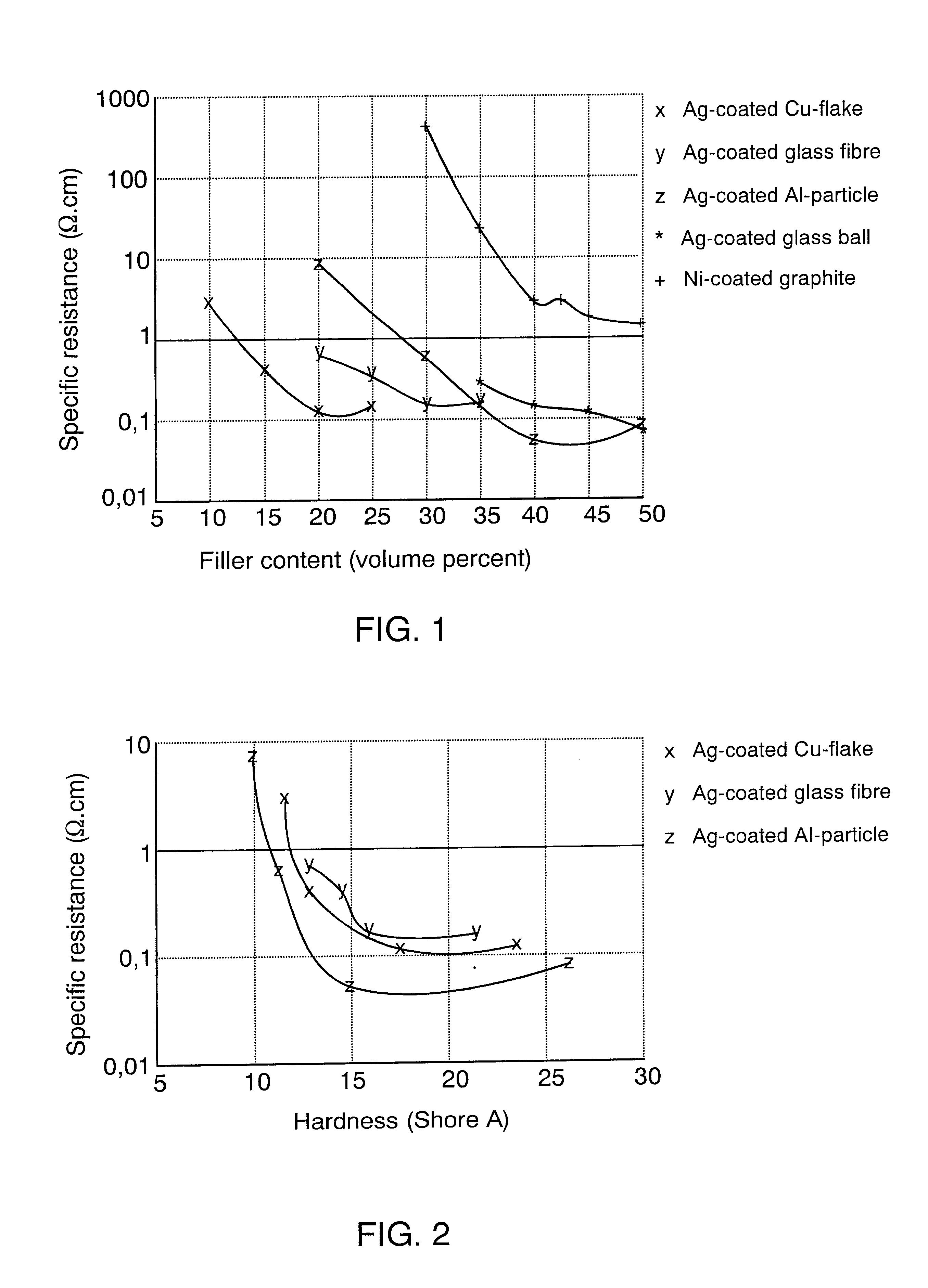
The TPE was formed of a matrix material and a filler, and test pieces were manufactured as described in example 1. The specific resistance of the TPE was determined as in example 1. The material hardness described in FIG. 2 was determined according to standards ASTM D2240 and DIN 53505 with a durometer type A.

As seen in FIG. 2, the hardness of the TPE of the invention using all fillers and filler contents measured in the example is in the range of 10 to 25 Shore A, which makes additional filling of the TPE possible using fire retardants or other application-specific additives, for instance, so that the material hardness remains at the level required of sealing materials. It should be noted that one TPE of the invention, injection-molded into a sealing, has reached an approximately 40 dB attenuation at the frequency range of 20 to 700 MHz. The specific resistance value measured in a corresponding TPE material is approximately 0.1 .OMEGA..cm. In other words, the TPE of the in...

Example

EXAMPLE 3

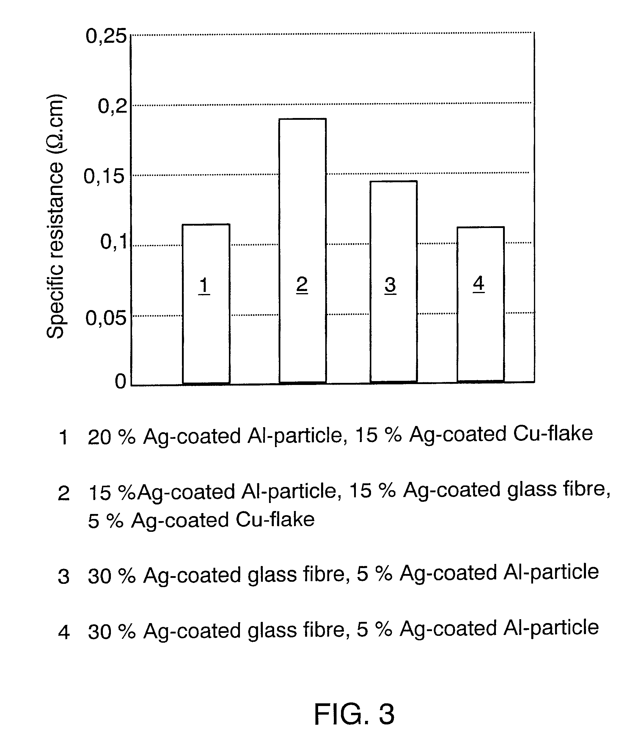
A SEPS-based matrix material (trade name Kraiburg TP1AAA) was melted in a mixer at an increased temperature in the same conditions as in example 1. Fillers were added one after the other and as quickly as possible to the melted matrix material, the fillers being:

Embodiment 1

20% silver-coated aluminium particles and 15% silver-coated copper flakes,

Embodiment 2

15% silver-coated aluminium particles, 15% silver-coated glass fiber and 5% silver-coated copper flakes,

Embodiment 3

30% silver-coated glass fiber and 5% silver-coated aluminium particles, and

Embodiment 4

30% silver-coated glass fiber and 5% silver-coated copper flakes.

After all the filler had been added to the matrix material, the torque curve of the mixer was allowed to even out, after which the mixing was continued for 4 to 6 minutes. Test pieces were made by compression molding from the mixed TPE stock for the purpose of determining the specific resistance, the determining being performed in the manner described in ex...

Example

EXAMPLE 4

A matrix material (SEPS-based Kraiburg TP1AAA or SEBS-based Elastoteknik 500120) and a filler were compounded in a twin-screw extruder at a screw rate of approximately 108 min.sup.-1 and with the set temperatures of the extruder zones being with TP1AAA in zone 1 at 60.degree. C., in zone 2 at 150.degree. C., and in zones 3 to 10 at 160.degree. C.; and with 500120, the temperatures being the same with the exception of zones 3 to 10, whose temperature was set at 180.degree. C. The behaviour of the viscosity of the TP1AAA matrix material can be presented in the following format:

.eta.=147.7405.multidot..gamma..sup.0.671878-1

and that of the 500120 material in the format:

.eta.=3173.134.multidot..gamma..sup.0.380459 -1.

Test pieces were made of the compounded materials by compression molding, and the specific resistance values were measured as described in example 1.

FIG. 4 shows that each TPE of the invention compounded in example 4 undershoots the specific resistance value 1 .OMEG...


PUM

PropertyMeasurementUnit
Fractionaaaaaaaaaa
Fractionaaaaaaaaaa
Electrical conductivityaaaaaaaaaa

Abstract

An electrically conductive thermoplastic elastomer and a sealing and/or EMI shielding product comprising a substantially electrically non-conductive matrix material and an electrically conductive filler part which contains metal. The specific resistance of the elastomer is at most 1 Omega.cm.

Description

This application is a Continuation of International Application PCT / F100 / 00173 filed Mar. 3, 2000 which designated the U.S. and was published under PCT Article 21(2) in English.The invention relates to an electrically conductive thermoplastic elastomer comprising a substantially electrically non-conductive matrix material and a filler part.The invention further relates to a sealing and / or an EMI shielding product.DESCRIPTION OF THE RELATED ARTThe continuous increase in electronic equipment has created a need, on one hand, to shield the equipment from electromagnetic interference caused by other electronic equipment and, on the other hand, to reduce the external interference the equipment itself causes. It is especially important to shield equipment whose operational malfunctions may cause physical injury, such as medical equipment and the control and navigational equipment in aircraft. The term EMI (electromagnetic interference) shielding is generally used to refer to the electromag...

Claims


Application Information

Patent Timeline
IPC IPC(8): C08K3/08C08K3/00H01B1/22H05K9/00
CPCC08K3/08H05K9/0015H01B1/22
Inventor KARTTUNEN, MIKKOMUSTONEN, JENNI
Owner PREMIX OY
Why Eureka
Try Eureka