

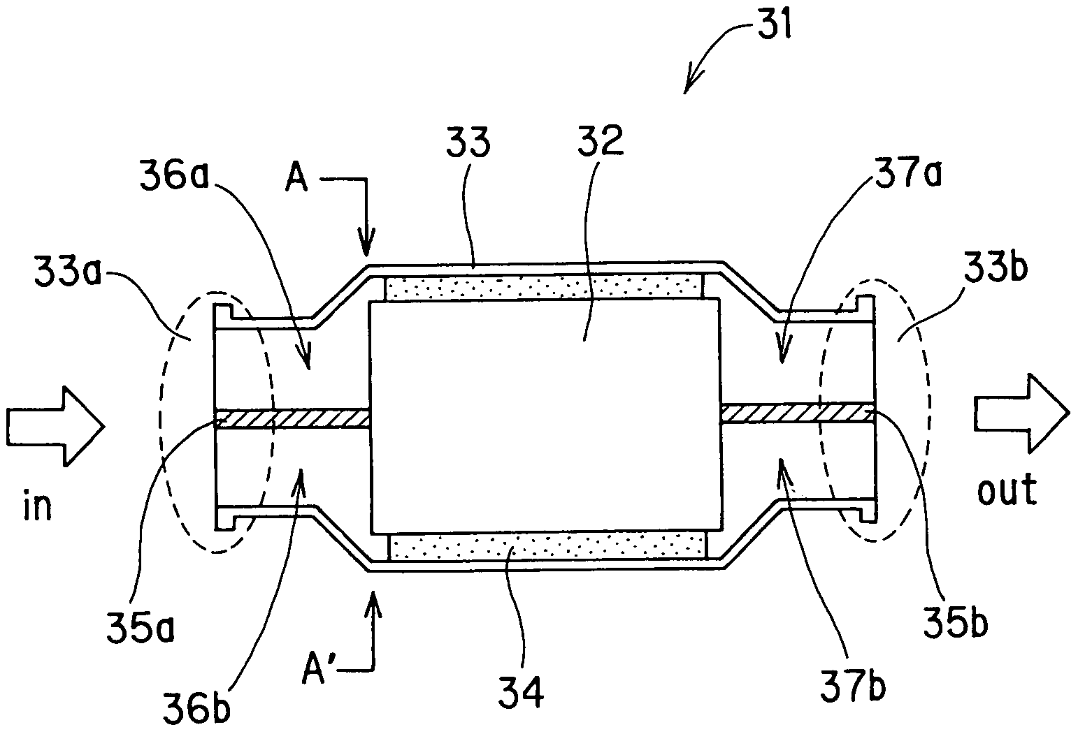
Honeycomb structure and catalytic converter
- Summary
- Abstract
- Description
- Claims
- Application Information
AI Technical Summary
Benefits of technology
Problems solved by technology
Method used
Image

Examples
example 1
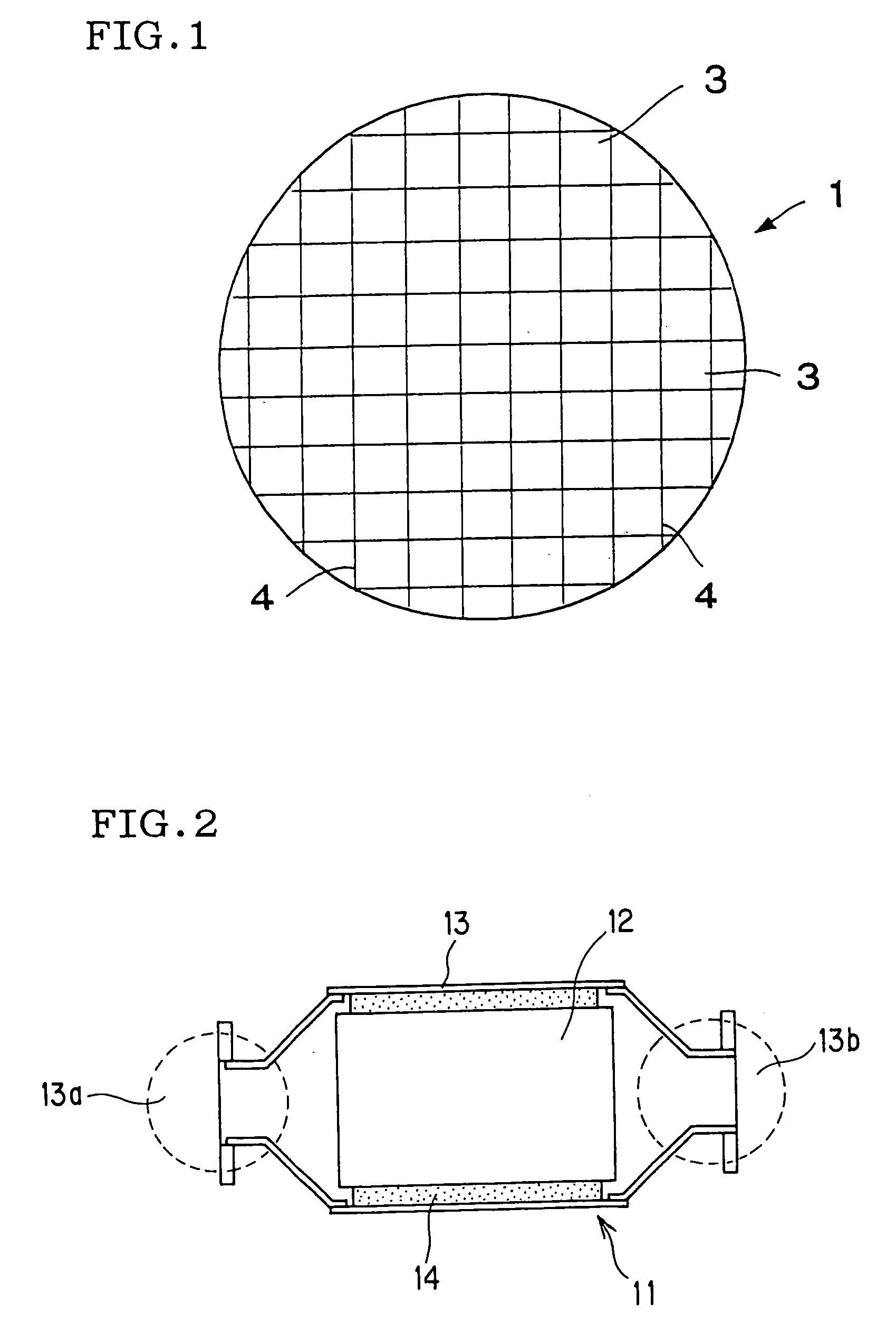
[0152] As the honeycomb structure for constituting a honeycomb catalyst body, there was used a honeycomb structure made of cordierite, which had a circular end face shape of 100 mm in diameter, a length of 100 mm, a square cell shape of 1.27 mm×1.27 mm, a partition wall thickness of 110 μm (4 mil), a cell density of 62 cells / cm2 (400 cells / in.2) and an outer peripheral wall thickness of 0.3 mm and wherein an internal wall 5 of 0.3 mm in thickness, such as shown in FIG. 5(a) and FIG. 5(b) was formed at the central portion. That is, there was used a honeycomb structure wherein a large number of cells were divided by an internal wall into left and right two cell blocks.
example 2
[0153] As the honeycomb structure for constituting a honeycomb catalyst body, there was used a honeycomb structure made of cordierite, which had a circular end face shape of 100 mm in diameter, a length of 100 mm, a square cell shape of 1.27 mm×1.27 mm, a partition wall thickness of 110 μm (4 mil), a cell density of 62 cells / cm2 (400 cells / in.2) and an outer peripheral wall thickness of 0.3 mm and wherein three thick partition walls 7 of 135 μm (5 mil) in thickness, such as shown in FIG. 7(a) and FIG. 7(b) were formed at the central portion. That is, there was used a honeycomb structure wherein a large number of cells were divided by thick partition walls into left and right two cell blocks.
example 3
[0154] As the honeycomb structure for constituting a honeycomb catalyst body, there was used a laminate such as shown in FIG. 13(a) and FIG. 13(b), of a first honeycomb structure 32c made of cordierite, which had a circular end face shape of 100 mm in diameter, a length of 60 mm, a square cell shape of 1.27 mm×1.27 mm, a partition wall thickness of 110 μm (4 mil), a cell density of 62 cells / cm2 (400 cells / in.2) and an outer peripheral wall thickness of 0.3 mm and a second honeycomb structure 32d made of cordierite, which had a circular end face shape of 100 mm in diameter, a length of 20 mm, a square cell shape of 2.54 mm×2.54 mm, a partition wall thickness of 430 μm (17 mil), a cell density of 15.5 cells / cm2 (100 cells / in.2) and an outer peripheral wall thickness of 0.5 mm.
[0155] In lamination of the first honeycomb structure 32c and the second honeycomb structure 32d, the two honeycomb structures were disposed so that the partition walls of the central portions of the two honeyco...
PUM
| Property | Measurement | Unit |
|---|---|---|
| Length | aaaaa | aaaaa |
| Length | aaaaa | aaaaa |
| Time | aaaaa | aaaaa |
Abstract
Description
Claims
Application Information