Fuel cell

a fuel cell and cell technology, applied in the field of fuel cells, can solve the problems of difficult to maintain the temperature of the cooling gas flow field, difficult to maintain the humidity in the membrane, and difficult to perform both cooling and humidification of the membrane, so as to achieve improved cooling efficiency, improved reliability, and adequate opening ratio

Inactive Publication Date: 2005-07-28
EQUOS RES
View PDF16 Cites 43 Cited by
  • Summary
  • Abstract
  • Description
  • Claims
  • Application Information

AI Technical Summary

Benefits of technology

[0015] By designing the opening ratio of the mesh conductor to be 25% or more, a sufficiently large contact area between the air as an oxidizing gas and the electrode is ensured. Further, by applying a treatment to the conductor so as to give it hydrophilic properties, the water adheres to and is retained on the mesh portion, and thus cooling efficiency is improved. Further, if the mesh conductor is made of metal mesh, punching metal, or expanded metal, the openings of the mesh conductor are distributed finely and uniformly, whereby an adequate opening ratio is achieved. Further, the mixed fluid passing through the openings of the contact surface with the electrode diffusion layer is stirred up, which enables the above described advantages to be achieved with greater reliability. Moreover, if expanded metal is used, contact resistance is small, because expanded metal has high rigidity with regard to thickness in comparison with other materials. Further, if the conductor is a corrugated plate, in comparison with the case in which a flat plate is used, it is possible to increase the proportion of the surface area that comes into contact with the diffusion layer, and, in addition, the amount of water that comes into contact with the corrugated plate is increased. As a result, cooling efficiency can be improved.

Problems solved by technology

In general, since the water generated in the electrochemical reaction is not sufficient for maintaining adequate moisture, it is necessary to provide a device for supplying water to each of the unit cells for humidification.
However, with the related disclosed technology, it is difficult to perform both cooling and humidification of the membrane.
As a result, it is difficult to maintain the temperature of the cooling gas flow field in the circulation passage.
For example, when the temperature increases in the air flow field having decreased in the circulation passage, moisture is removed from the electrolyte membrane, which makes it is difficult to maintain the humidity in the membrane.
Further, with the technology disclosed in Japanese Patent Application Laid Open No. 06-338338, even though the vapor is supplied through the porous wall surface, it may be difficult to achieve sufficient supply of vapor by using the moisture passing through the porous wall surface.
Further, in the cooling water passage, cooling is only performed using the sensible heat.
Therefore, in order to perform sufficient cooling, substantial amounts of energy or a mechanical device for circulation of the cooling water may be required.

Method used


Image

  • Fuel cell
  • Fuel cell
  • Fuel cell

Examples


first embodiment

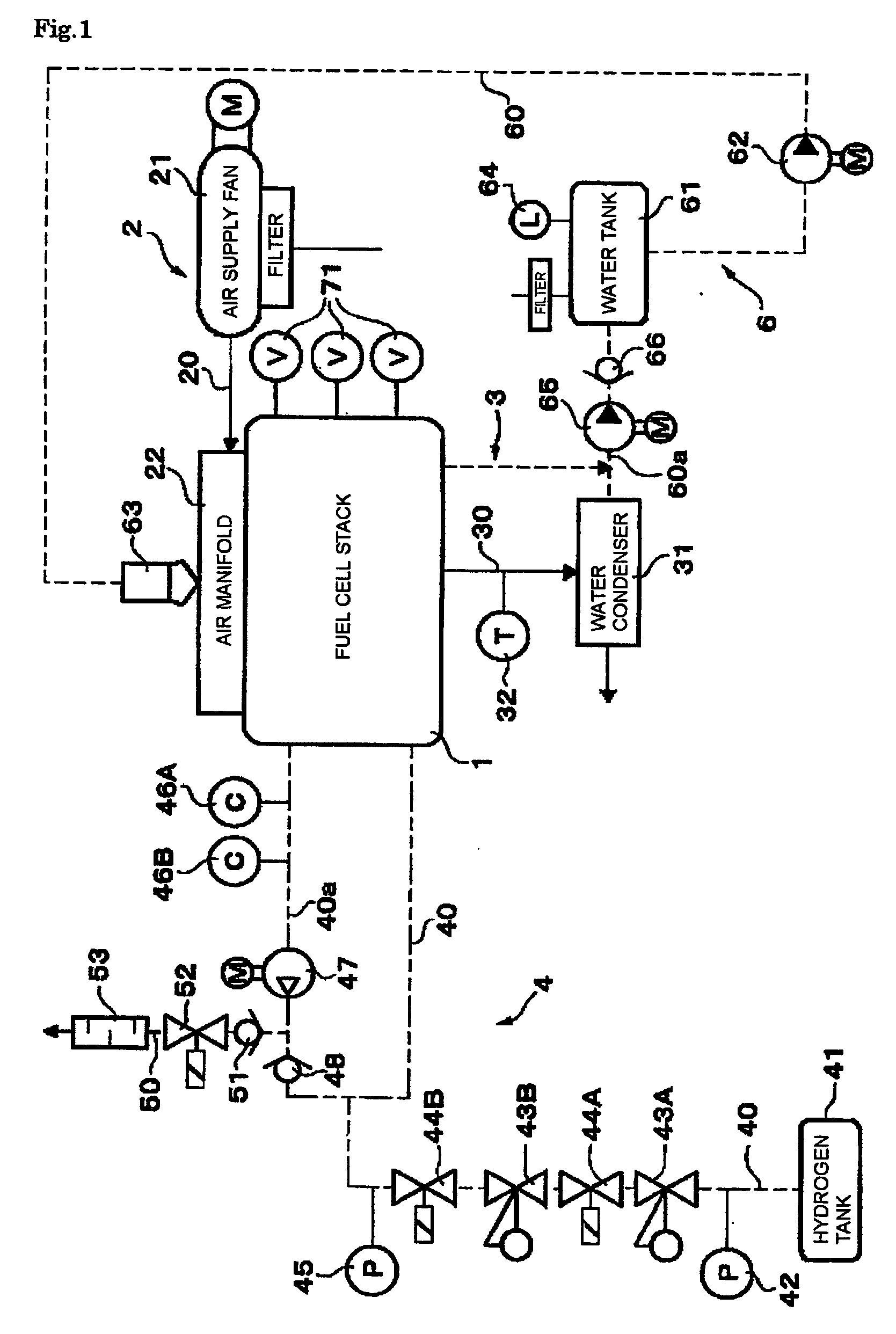
[0026] Hereinafter, embodiments of the present invention will be described with reference to the drawings. Firstly, FIGS. 1 to 7 show a first embodiment of the present invention. FIG. 1 is a view showing an exemplary structure of a fuel cell system for use in a vehicle; the fuel cell system includes a fuel cell stack 1 according to the present invention. The fuel cell system includes a fuel cell main unit with the fuel cell stack 1 as a main component, an air supply system 2 (see the solid lines in FIG. 1), and an air discharge system 3. The air supply system 2 includes an air supply fan 21 that acts as an air supply device for supplying air to the fuel cell system 1, and the air discharge system 3 includes a water condenser 31. Further, the fuel cell system also includes a fuel supply system 4 (see the two dot chain lines in FIG. 1) and a water supply system 6 (see the broken lines in FIG. 1). The fuel supply system 4 includes a hydrogen tank 41 that acts as a hydrogen supply devic...

second embodiment

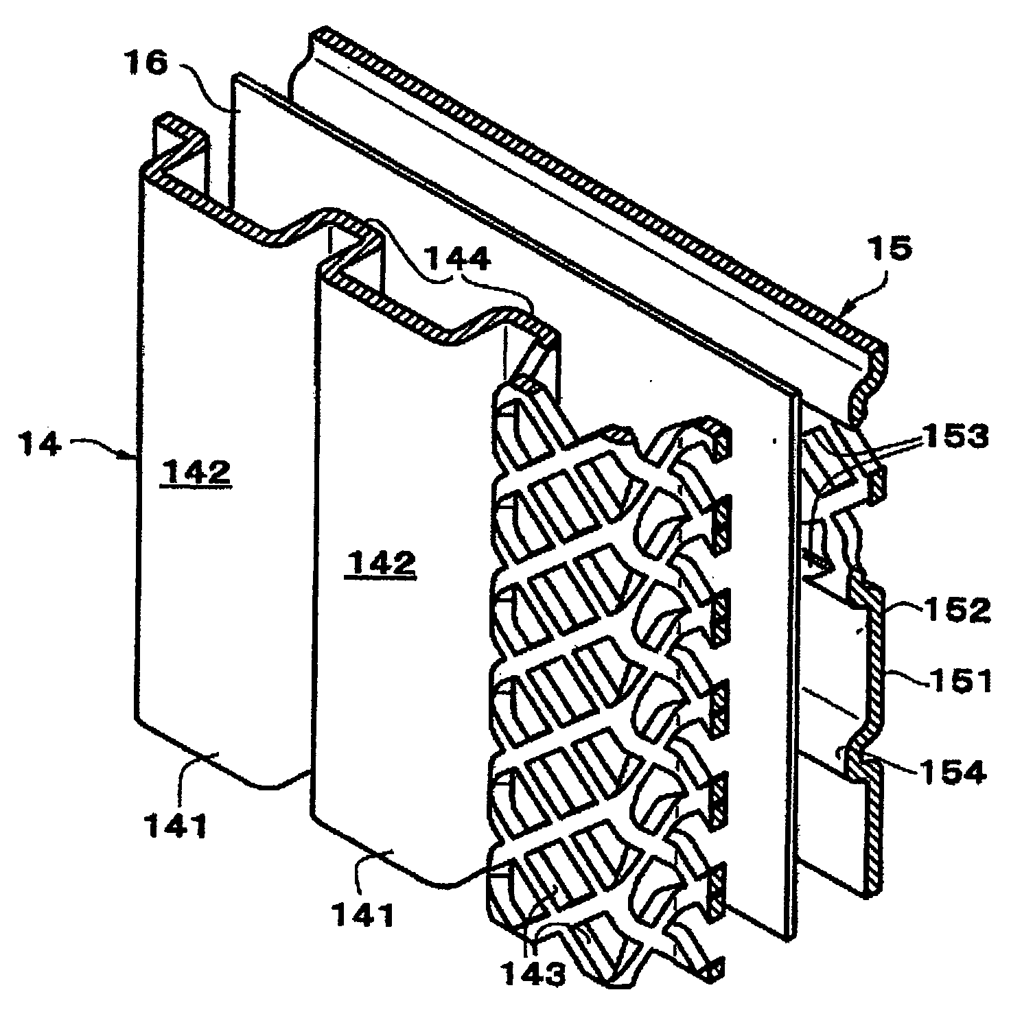
[0048] In a second embodiment shown in FIG. 8, both of the collectors 14 and 15 are made, as an example, of punching metal. Further, in this case, in order to use common material for both of the collectors 14 and 15, the dimensions of the corrugations, i.e., the height and the pitch of the corrugations, are the same as those of the fuel electrode side collector according to the first embodiment. When this structure is adopted, in order to achieve sufficient sectional area of the flow field on the air electrode side where the height of the corrugations is low, the separator 16 also has protruding corrugations 161, which protrude toward the collector 14 and which are spaced so as to match the spacing of the grooves 144 of the collector 14. As a result of this configuration, the separator base plate 16 has a corrugated plate-like shape. In the following description, the structural elements that are identical to those of the first embodiment are denoted with the same reference numerals,...

third embodiment

[0051] In the third embodiment shown in FIG. 9, as with the second embodiment, both of the collectors 14 and 15 are made of punching metal. However, the third embodiment differs from the second embodiment in that the collector 15 of the fuel electrode side is a flat plate without any corrugations. In this example, in order to achieve sufficient sectional area of the flow fields on both sides of the air electrode and the fuel electrode, the separator base plate 16 has protruding corrugations 161 and 162 protruding toward the air electrode and the fuel electrode from a base surface of the base plate 16. The other structural elements of the third embodiment are identical to those of the second embodiment. Therefore, these structural elements are denoted with the same reference numerals, and description thereof will be omitted.


PUM

PropertyMeasurementUnit
thicknessaaaaaaaaaa
thicknessaaaaaaaaaa
electrical currentaaaaaaaaaa

Abstract

A fuel cell includes a separator (10B) interposed between adjacent unit cells (10A). A mixed fluid of air and water is supplied to an air electrode (12) of each unit cell. The separator includes a mesh conductor (14) on at least a surface facing the air electrode of the unit cells, and the mixed fluid passes through the mesh conductor. Water is retained on the mesh portion of the conductor. With this configuration, it is possible for the unit cell to be cooled by the release of latent heat when the water is evaporated by the heat of unit cell, without any clogging which inhibits contact between the electrode and the air.

Description

INCORPORATION BY REFERENCE [0001] The disclosure of Japanese Patent Application No. 2004-014402 filed on Jan. 22, 2004 including the specification, drawings and abstract is incorporated herein by reference in its entirety. BACKGROUND OF THE INVENTION [0002] 1. Field of the Invention [0003] The present invention relates to a fuel cell, and in particular, to a technology for cooling the fuel cell using a separator interposed between unit cells of the fuel cell. [0004] 2. Description of the Related Art [0005] A unit cell of a PEM fuel cell, which is one type of fuel cell, includes a fuel electrode (also referred to as the “hydrogen electrode” since hydrogen gas is generally used as the fuel), an oxidant electrode (likewise, hereinafter referred to as the “air electrode” since air, as an oxygen-containing gas, is used as the oxidant), and a solid polymer electrolyte membrane interposed between the fuel electrode and the air electrode. The fuel electrode and the air electrode each includ...

Claims


Application Information

Patent Timeline
Patent Type & Authority Applications(United States)
IPC IPC(8): H01M8/02H01M8/04H01M8/10H01M8/24
CPCH01M8/0228H01M8/0232H01M8/0254H01M8/0267Y02E60/50H01M8/04097H01M8/04291H01M2008/1095H01M8/04059H01M8/241H01M8/2483H01M8/0258H02J13/00H02J7/35H02J7/0047Y02B20/72
Inventor HORIGUCHI, MUNEHISA
Owner EQUOS RES
Why Eureka
Try Eureka