High-power LGA socket

a high-power, lga socket technology, applied in semiconductor devices, solid-state devices, basic electric elements, etc., can solve the problems of device input/output elements that are required, and limited current carrying capacity of land grid array packages

Inactive Publication Date: 2005-07-28
INTEL CORP
View PDF24 Cites 1 Cited by
  • Summary
  • Abstract
  • Description
  • Claims
  • Application Information

AI Technical Summary

Benefits of technology

[0028] The structure and method of this invention has many advantages. Among the advantages is that the structure meets a growing demand for high loads and evenly distributed loads on a die package. The structure is capable of carrying high loads and distributing these loads substantially evenly over the die package since the structure uses a separate slot, and separates the current carrying function from the lands of the land grid array package. Thus, the land grid array packaging method and apparatus described allows for higher current carrying portions, mainly for delivering power to the die, in the simple, high contact density, low inductance land grid array package. The problem of a short wiping distance is eliminated because the wiping distance is lengthened when the die package is moved vertically across the socket and into the slot at one end of the base of the socket. The longer wiping distance assures a reliable, good electrical contact between the contacts in the socket and the individual lands of the die package.

Problems solved by technology

In the past few years, however, many semiconductor devices have required more input / output elements than provided in a peripherally leaded package.
However, the land grid array packages have technical limitations that stand in the way of wide acceptance of this technology in a useable product.
The technical limitations include the fact that land grid array packages have limited current carrying capability.
Simply put, the capability of the individual lands to carry power is limited due to the small size of the land grid array and the electrical connections made to the land grid array.
This limits the amount of power that can be input to such packages.
Another technical problem with land grid array packages is that there is a short wiping distance between the land and the contact as the contact is initially placed in contact with the land.
Current land grid array packages have difficulty in handling a high load and difficulty in distributing the load on the packages evenly.
This lacking is yet another technical hurdle that stands in the way of acceptance of land grid arrays becoming a widely used packaging technique in various products.

Method used


Image

  • High-power LGA socket
  • High-power LGA socket
  • High-power LGA socket

Examples


Embodiment Construction

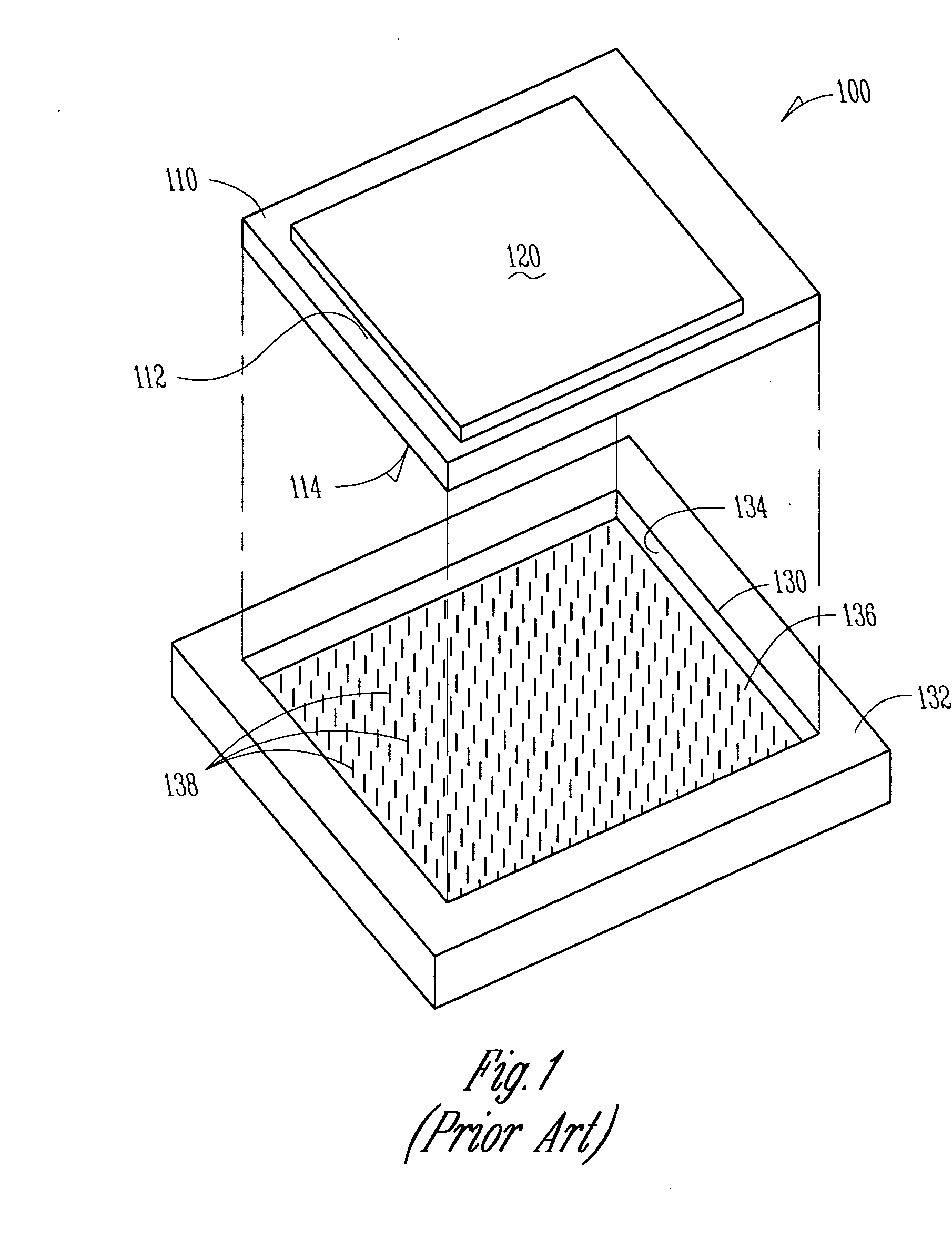
[0019]FIG. 1 illustrates a perspective top view of a prior art land grid array type package 100. The land grid array package includes a substrate 110 to which a die 120 is attached. The substrate includes a first major surface 112 and a second major surface 114. The die 120 is attached to the first major surface 112 of the substrate 110. Located on the second major surface 114 of the substrate 110 is an array of lands. The lands carry both input / output signals to and from the electronics located within the die 120, as well as the current for power as required by the electronics within the die 120. Thus, the land grid array type package 100 of the prior art has the land carrying both the currents necessary for power, as well as the signal level currents for input and output to the electronics within the die 120. The die 120 fits within a corresponding socket 130 that includes a base 132 having an opening 134 therein. At the bottom of the opening 134 is a major surface 136, which incl...


PUM

PropertyMeasurementUnit
angleaaaaaaaaaa
currentsaaaaaaaaaa
currentaaaaaaaaaa

Abstract

A system for providing electrical contacts between a die and an electrical device includes a die and a package. The package includes a first major surface, a second major surface, a first scalloped edge, a second scalloped edge and a solid end adapted for insertion into a slot. The solid end and the scalloped edges carry current greater than the current needed for an input / output signal. The socket includes a base having an opening therein adapted to receive the package. A slot is located at one end of the opening in the base. The slot is provided with a plurality of conductors for carrying currents greater than the current needed for an input / output signal. A first edge and second edge of the opening include a plurality of spaced overhangs positioned over the opening. The overhangs are sloped with respect to the major planar surface.

Description

RELATED APPLICATION(S) [0001] This application is a divisional of U.S. application Ser. No. 10 / 159,084, filed on May 29, 2002 which is incorporated herein by reference.FIELD OF THE INVENTION [0002] The present invention relates to a package for a semiconductor device, and specifically to a package for semiconductor devices that use a land grid array. BACKGROUND OF THE INVENTION [0003] As more and more capability is being designed into semiconductor devices, such as memory modules and microprocessors, there are an increasing number of leads or input / output elements being placed onto electronics packages. In the past, peripherally leaded packages provided an adequate number of leads or input / output elements. Peripherally leaded packages have leads or input / output elements along the edges of the electronic component. In many applications, such packages provide an adequate number of input / output elements. In the past few years, however, many semiconductor devices have required more inpu...

Claims


Application Information

Patent Timeline
Patent Type & Authority Applications(United States)
IPC IPC(8): H01L23/498H01L23/50
CPCH01L23/49805H01L23/50Y10T29/41H01L2924/0002H01L2924/00
Inventor TRAN, DONALD T.
Owner INTEL CORP
Why Eureka
Try Eureka