Y-pattern piston check valve, piston valve assembly for a Y-pattern piston check valve, and method

a check valve and piston valve technology, applied in the field of y-pattern piston check valves, can solve the problems of increasing the number of assembly steps required, increasing the cost of the valve, so as to achieve quick, easy, economical and durable manufacturing.

Inactive Publication Date: 2005-08-04
AROV GENNADY +1
View PDF24 Cites 29 Cited by
  • Summary
  • Abstract
  • Description
  • Claims
  • Application Information

AI Technical Summary

Benefits of technology

[0033] It is an advantage of the present invention in that a valve is provided that can be quickly, easily, economically, and durably fabricated.
[0034] It is another advantage of the present invention in the valve is provided that is durable, long-lasting, reliable, and repeatable.
[0035] Other objects, features, and advantages of the present invention will become apparent to those skilled in the art from the detailed descri

Problems solved by technology

The valve bonnet has a guide extending from it that appears to be a component separate from the bonnet, which increases cost and the number of manufacturing steps required.
Furthermore, this valve also has valve seat separate from the valve body, which is an additional component that adds to the cost of the valve and increases the number of assembly steps required.
These flutes add to the cost to make the valve and increase the complexity of the valve, all of which increases costs and requires additional manufacturing steps.
All of these additional components cost money and require additional assembly steps, all of which increase valve cost.
Unfortunately, the valve body is of non-standard design and is limited to air flow control applications.
In addition, because the surface area of the rear face of the disc holder assembly is small relative to the front face of the valve disc and nut, response time is undesirably slow, also making it unacceptable for liquid flow control applicat

Method used


Image

  • Y-pattern piston check valve, piston valve assembly for a Y-pattern piston check valve, and method
  • Y-pattern piston check valve, piston valve assembly for a Y-pattern piston check valve, and method
  • Y-pattern piston check valve, piston valve assembly for a Y-pattern piston check valve, and method

Examples


Embodiment Construction

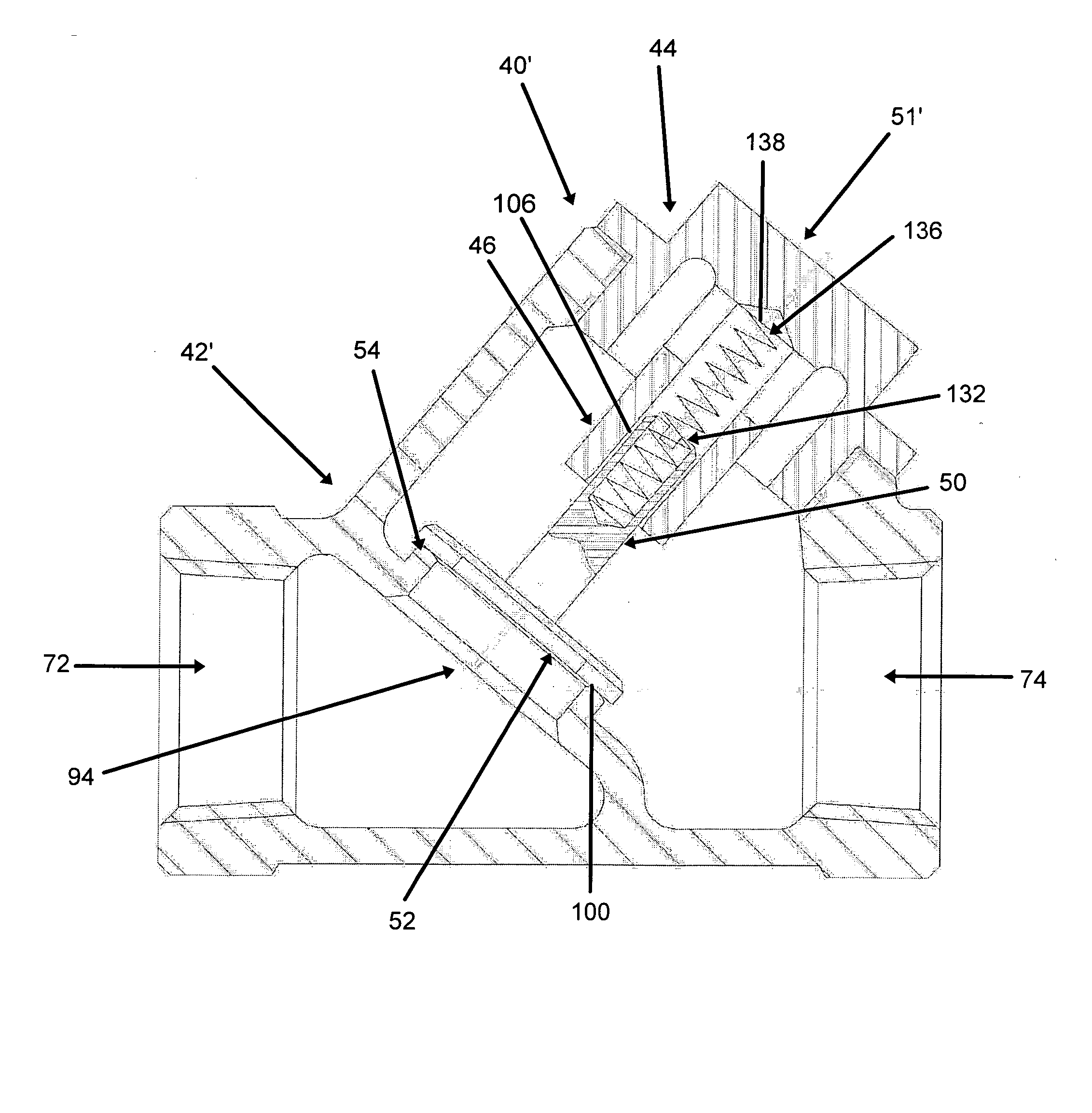
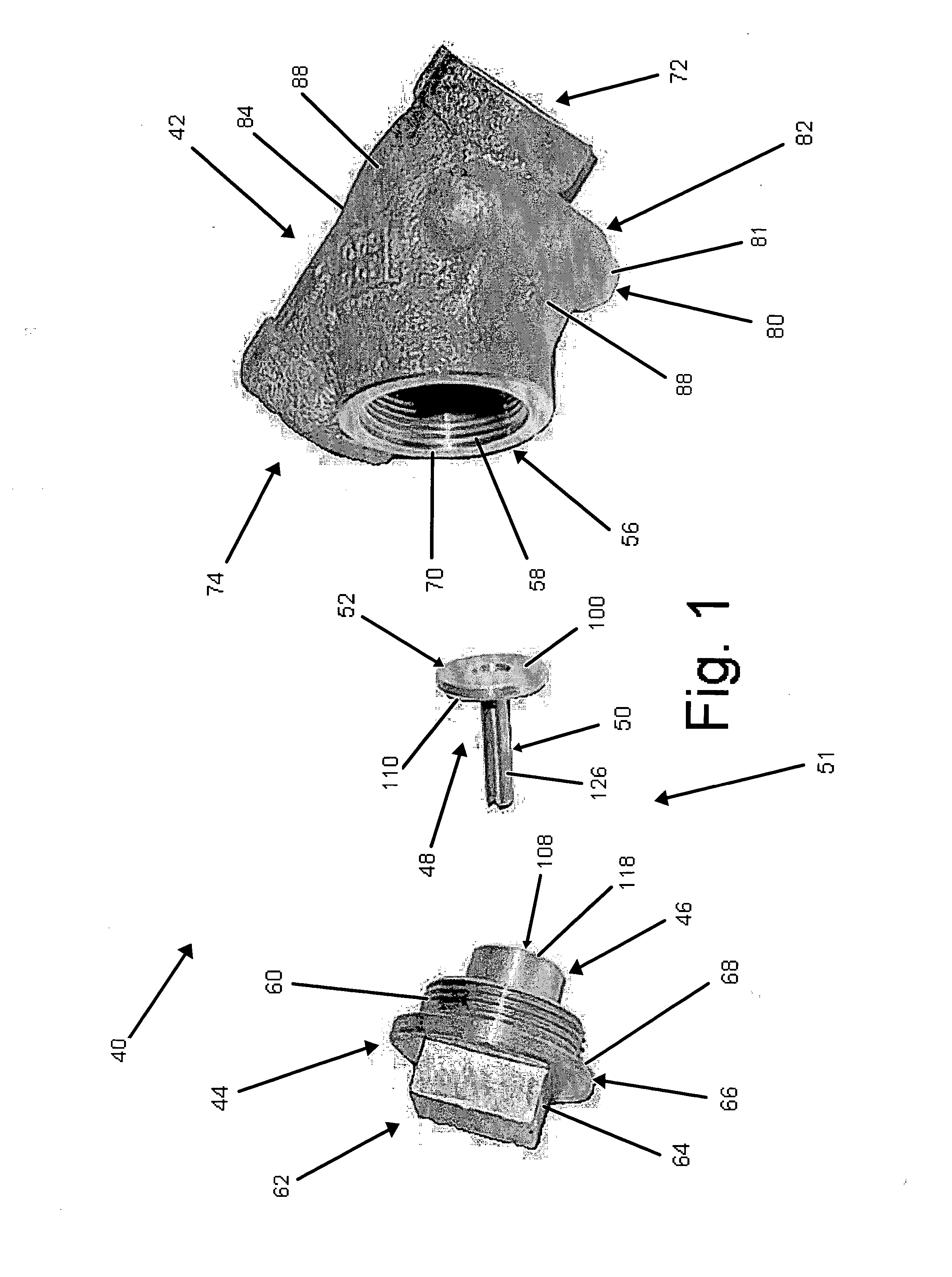
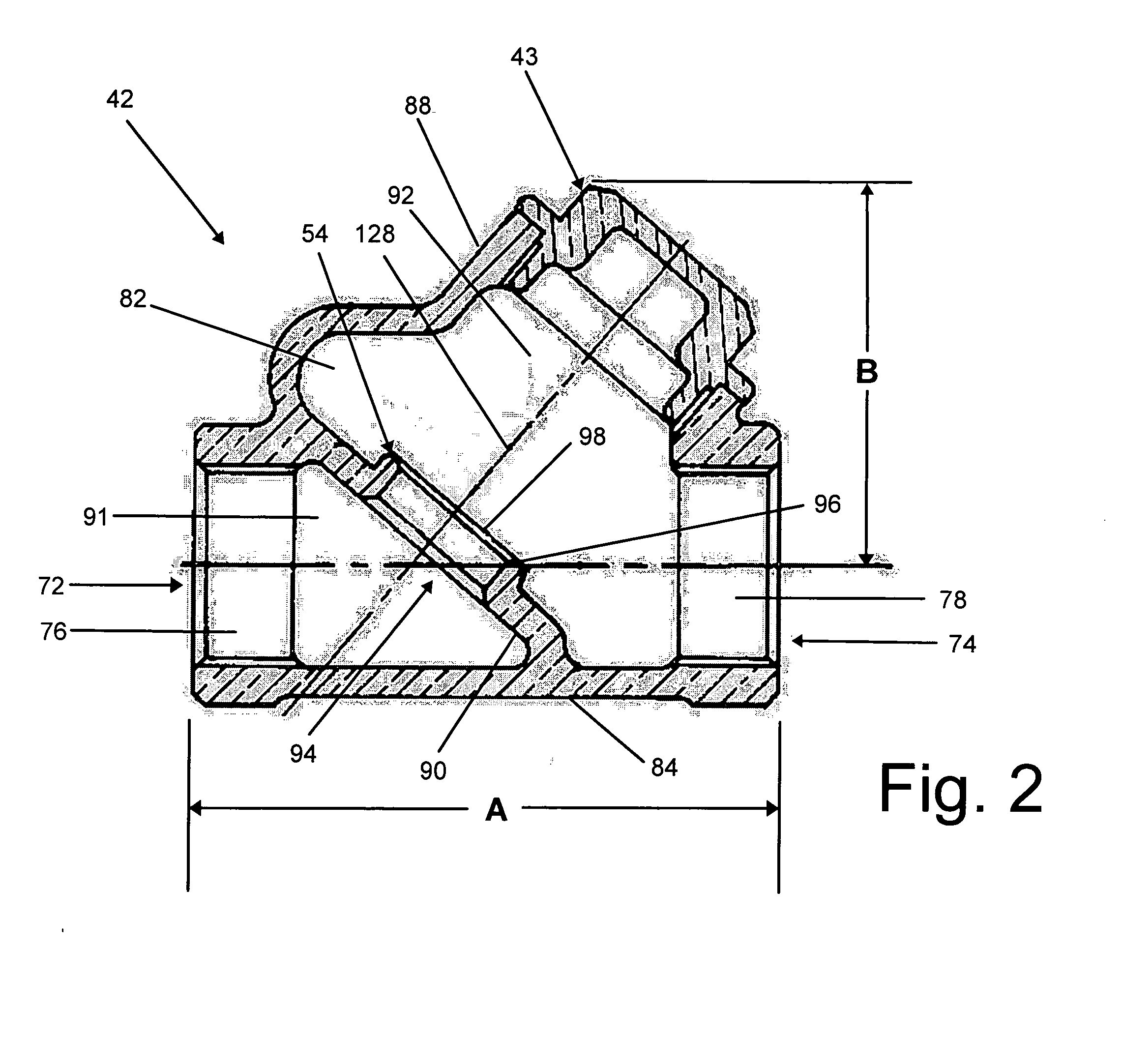
[0052]FIG. 1 illustrates a preferred embodiment of a Y-pattern piston check valve 40 constructed in accordance with the invention that includes a Y-pattern valve body 42, a bonnet or cap 44 that threadably attaches to the valve body 42 and that has an outwardly extending valve stem guide 46, and a valve piston 48 that includes an outwardly extending elongate valve stem 50 reciprocably received in the guide 46. During operation, fluid flow is permitted through the valve 40 when the piston 48 is located in an open position and fluid flow is opposed when the piston 48 is located in a closed position.

[0053] The valve 40 is constructed such that some space is intentionally provided between the valve stem 50 and the valve stem guide 46 to permit the piston 48 to adjust and fluidtightly seal when closing despite some mislocation and / or misalignment between the cap 44 and valve body 42. This space is provided by making the outer diameter of the valve stem 50 smaller than the inner diameter...


PUM


Abstract

A valve that includes a valve body in which a valve piston is disposed. The valve piston has a disc and an elongate stem that is reciprocably carried by a valve guide. The valve guide is part of an assembly that includes an cap that is attached to a Y-pattern valve body. The valve body has a valve seat that preferably is an integral hard seat and the disc has a sealing surface that preferably is a hard surface. Where operation independent of the effects of gravity is desired, a biasing element, preferably a coil spring captured in compression, is disposed in communication with the valve guide and the stem of the piston. A tolerance is provided between the stem and guide that permits angular and lateral adjustment of the disc during closing that compensates for mislocation and/or misalignment between the cap and valve body.

Description

CROSS REFERENCE TO RELATED APPLICATION [0001] This application claims priority under 35 U.S.C. §119(e) in U.S. Provisional Patent Application No. 60 / 541,139, filed Jan. 31, 2004, the entirety of which is expressly incorporated herein by reference.FIELD OF THE INVENTION [0002] The present invention is directed to a Y-pattern piston check valve and more particularly to a Y-pattern piston check valve capable of using a horizontal swing check Y-pattern valve body, a piston valve assembly that includes a cap construction therefor, as well as a method of fabrication and assembly. BACKGROUND OF THE INVENTION [0003] There are countless types and configurations of valves used in controlling and regulating fluid flow. One particular type of valve is a check valve used to permit fluid flow in one direction and prevent fluid flow in the opposite direction. While there are many types of check valves, only a few types are used in the vast majority of commercial and industrial applications having ...

Claims


Application Information

Patent Timeline
IPC IPC(8): F16K15/06
CPCF16K15/063Y10T137/7934
Inventor AROV, GENNADYSTEIN, DAVID
Owner AROV GENNADY
Why Eureka
Try Eureka