Process and apparatus for boiler tube panel welding and straightening

a technology of boiler tube panel and process, applied in the direction of welding apparatus, non-electric welding apparatus, manufacturing tools, etc., can solve the problems of deterioration from corrosion, particularly in the form of bowing or bending of the panel, and the particular problem of distortion of the panel, so as to reduce the incidence of cold laps

Active Publication Date: 2005-08-04
GENERAL ELECTRIC CO
View PDF6 Cites 21 Cited by
  • Summary
  • Abstract
  • Description
  • Claims
  • Application Information

AI Technical Summary

Benefits of technology

[0009] According to optional but preferred aspects of the invention, the apparatus includes electronic circuitry that provides better control of the overlay welding head and various parameters of the overlay welding operation. For example, the apparatus preferably includes a feedback capability that can address errors and failures of various components of the welding apparatus, including shielding gas, carriage travel, etc., thereby reducing the incidence of cold laps, burn-throughs, and overlay deposited with improper shielding gas pressure. The invention utilizes the above improvements and preferred aspects to provide an apparatus and process that are capable of consistently producing an undistorted boiler tube panel, yet the apparatus and process are sufficiently uncomplicated to be used by operators with limited experience.

Problems solved by technology

Distortion has been a particular problem encountered when overlay welding boiler tube panels prior to installation as a result of the large size of tube panels (for example, about fifty feet (about fifteen meters) in length and about six feet (about two meters) in width) and the relatively large heat input of GMAW and GTAW welding process.
Distortion in the form of bowing or bending of a panel is particularly likely when welding is performed on only one side of the panel, e.g., the side that will face the interior of the boiler and therefore most likely to be deteriorated from corrosion.

Method used


Image

  • Process and apparatus for boiler tube panel welding and straightening
  • Process and apparatus for boiler tube panel welding and straightening
  • Process and apparatus for boiler tube panel welding and straightening

Examples


Embodiment Construction

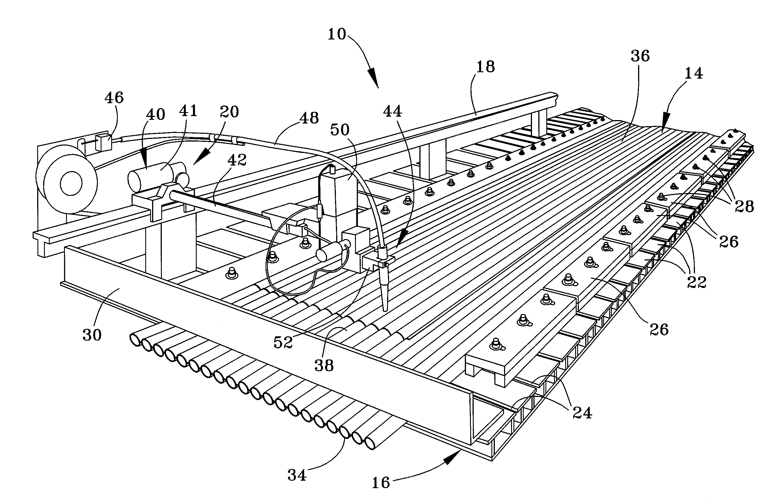
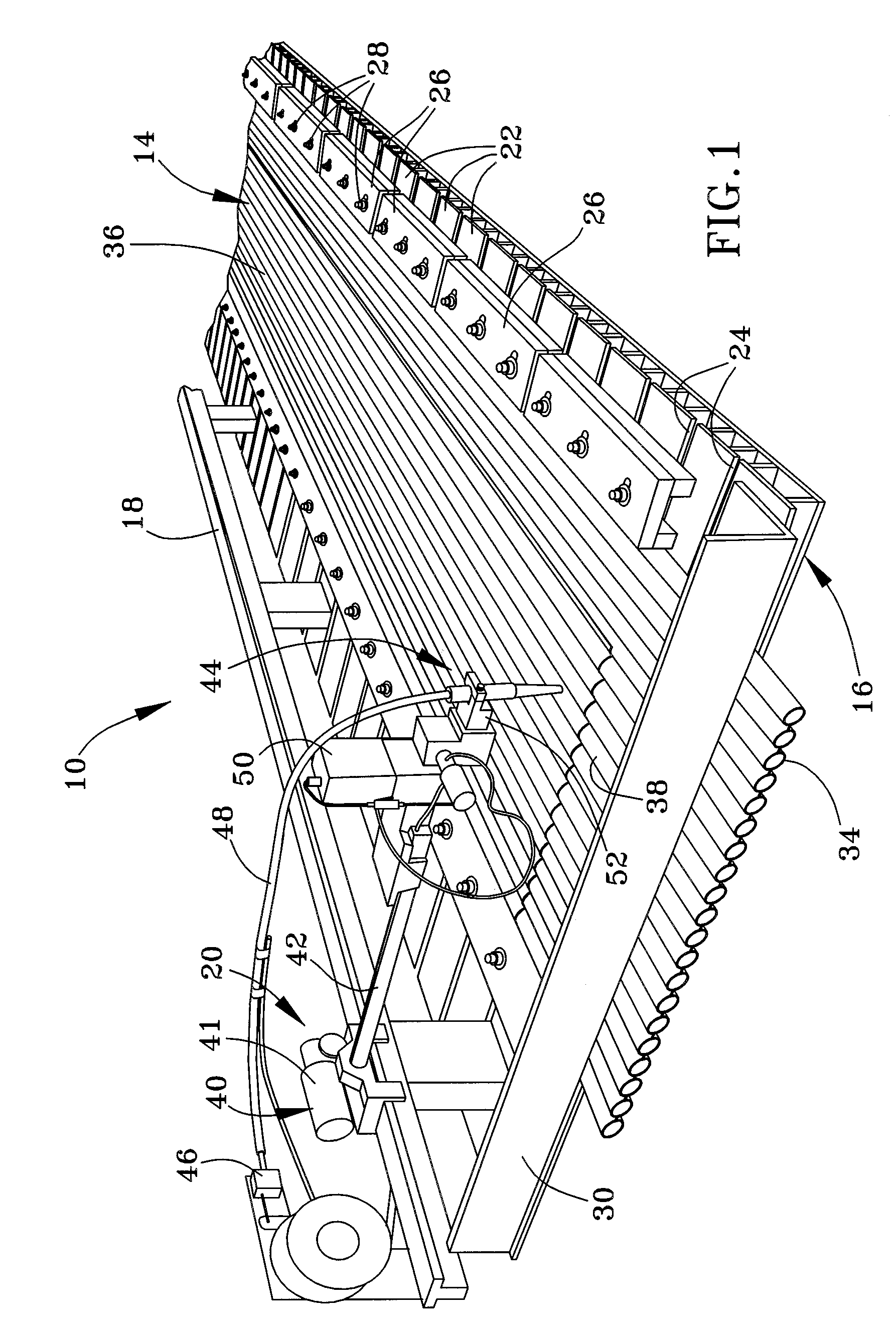
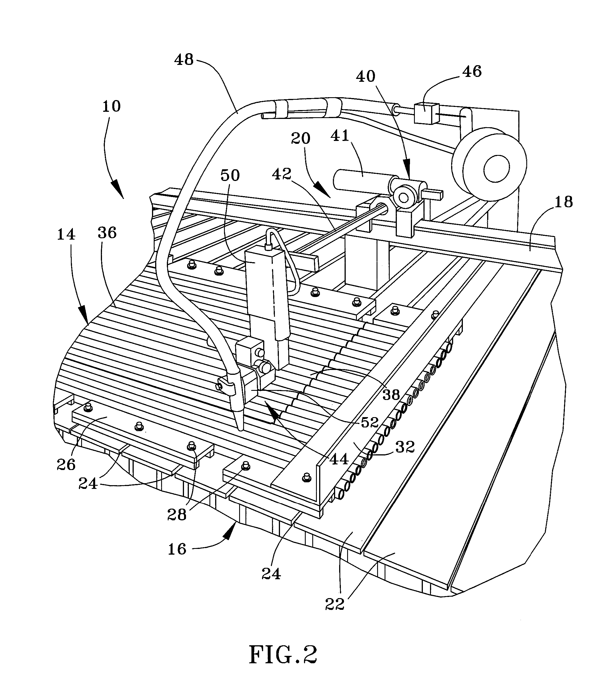
[0016]FIGS. 1 and 2 depict an overlay welding apparatus 10 and FIGS. 4 and 5 depict a straightening apparatus 12 in accordance with a preferred embodiment of the invention. As seen in FIGS. 1 and 2, which depict opposite ends of the welding apparatus 10, a boiler tube panel 14 is shown as being horizontally supported on the apparatus 10, with the lower surface 34 of the panel 14 being contacted by an elongate frame 16 and the upper surface 36 of the panel 14 facing upward. The frame 16 is shown as being constructed of individual frame members 22 oriented in a transverse direction to the panel 14 and frame 16, and spaced apart to define slots 24 between adjacent frame members 22. Retaining members 26 are shown as secured to the frame 16 with bolts 28 anchored in the slots 24, enabling the retaining members 26 to be adjusted transversely inward and outward relative to the panel 14 for gripping the lateral edges of the panel 14. The frame 16 further includes a header bar 30 for securin...


PUM

PropertyMeasurementUnit
widthaaaaaaaaaa
lengthaaaaaaaaaa
lengthaaaaaaaaaa

Abstract

An apparatus and process for depositing an overlay weld on a boiler tube panel comprising a plurality of tubes with adjacent tubes joined together with membranes therebetween, and then straightening the panel in response to bowing that occurs as a result of depositing the overlay weld. The apparatus generally comprises an overlay welding apparatus that deposits an overlay weld on a surface of a boiler tube panel, and a straightening apparatus for straightening the panel following deposition of the overlay weld. The straightening process entails placing the boiler tube panel between two members, and the pressing a portion of the panel therebetween.

Description

BACKGROUND OF INVENTION [0001] 1. Field of the Invention [0002] The present invention generally relates to welding equipment and processes. More particularly, this invention relates to a welding apparatus and process for depositing an overlay weld on a boiler tube panel and then straightening the panel for installation in a boiler. [0003] 2. Description of the Related Art [0004] Overlay welding generally involves depositing weld material over a surface region in a series of beads with some lateral overlapping, forming a continuous layer of weld material that increases the thickness and strength of the region. Overlay welds are often deposited by shielded metal-arc welding (including gas metal arc welding (GMAW) and gas tungsten arc welding (GTAW)) in the restoration of tubes and large vessels used in industries such as utilities, co-generation refining, petrochemical, pulp and paper, and waste-to-energy. Particular uses of overlay welds include reinforcing and repairing individual b...

Claims


Application Information

Patent Timeline
Patent Type & Authority Applications(United States)
IPC IPC(8): B23K9/12
CPCY10T29/49393B23K9/126
Inventor KISLOVSKY, VICTORMOSS, WARREN T.ROHAUS, RICHARD WAYNE
Owner GENERAL ELECTRIC CO
Why Eureka
Try Eureka