
Receiver electronics proximate antenna

a technology of receiver electronics and proximal antennas, which is applied in the direction of optical radiation measurement, survey, semiconductor/solid-state device details, etc., can solve the problems of weak analog signals, weak signals at the nano-volt level, and signal quality degradation of waveform signals. , to achieve the effect of reducing the number of proximal antennas

Active Publication Date: 2005-08-04
HALLIBURTON ENERGY SERVICES INC +1
View PDF9 Cites 9 Cited by
  • Summary
  • Abstract
  • Description
  • Claims
  • Application Information

AI Technical Summary

Benefits of technology

[0016] Efforts have been made to design electronics for use at high temperatures (i.e., above 185° Celsius). However, these efforts have not yielded an ideal, or in many cases even satisfactory, solution. For example, because the electronics are resident in the borehole for only a limited time, the electronics may be shielded from the elevated temperatures by insulation, heat-absorbing materials, and / or active refrigeration. These traditional approaches to configuring electronics for elevated temperature operation have been motivated by the poor performance of many electronics when they are directly exposed to environments with temperatures above 185 Celsius. However, these approaches greatly increase the size of the electronics package, and in the case of active refrigeration, greatly increase the energy consumption by the electronics package. Further, these approaches have not suggested a solution for providing electronics that can remain resident in a well indefinitely.

Problems solved by technology

A problem common to conventional designs is the degrading signal quality of the waveform signal as it is transmitted from the receiver to the controller.
The wiring between the antennas and the controller carries weak (nano-volt level) analog signals, however.
This makes these signals susceptible to noise, grounding, pick-up, cross-talk and vibration issues.
Each of these issues adversely affects the ability to measure phase shift and signal amplitude accurately, and therefore measurements of formation resistivity.
At temperatures approaching 180° Celsius, the performance of existing electronic technologies degrades or fails.
At high temperatures, CMOS electronics tend to be subject to significant leakage.
Also, the threshold gate voltages tend to change with temperature, making electronics performance unreliable.
Over time, metal migration tends to degrade performance of the electronics when these electronics are exposed to high temperature.
However, these efforts have not yielded an ideal, or in many cases even satisfactory, solution.
These traditional approaches to configuring electronics for elevated temperature operation have been motivated by the poor performance of many electronics when they are directly exposed to environments with temperatures above 185 Celsius.
However, these approaches greatly increase the size of the electronics package, and in the case of active refrigeration, greatly increase the energy consumption by the electronics package.
Further, these approaches have not suggested a solution for providing electronics that can remain resident in a well indefinitely.
Space limitations downhole can be severe, and part prevent design or installation of a cooling system to cool these electronics even if it were otherwise feasible.

Method used


Image

  • Receiver electronics proximate antenna
  • Receiver electronics proximate antenna
  • Receiver electronics proximate antenna

Examples


Embodiment Construction

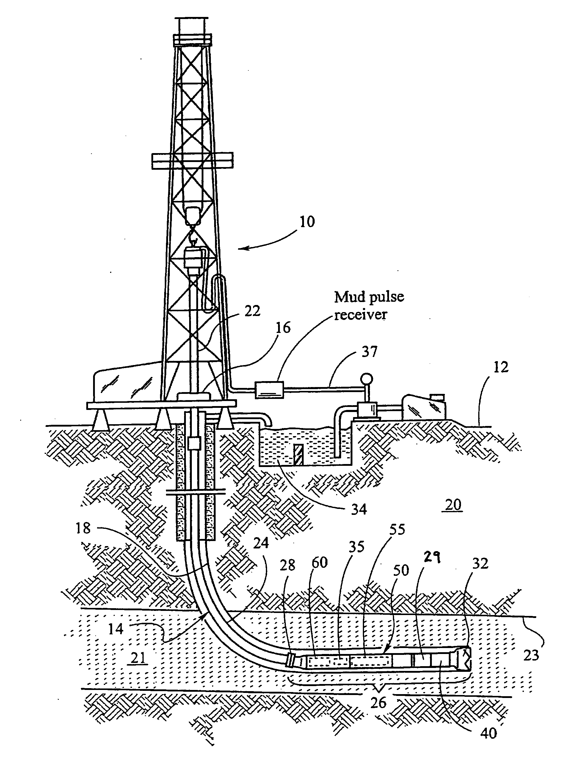
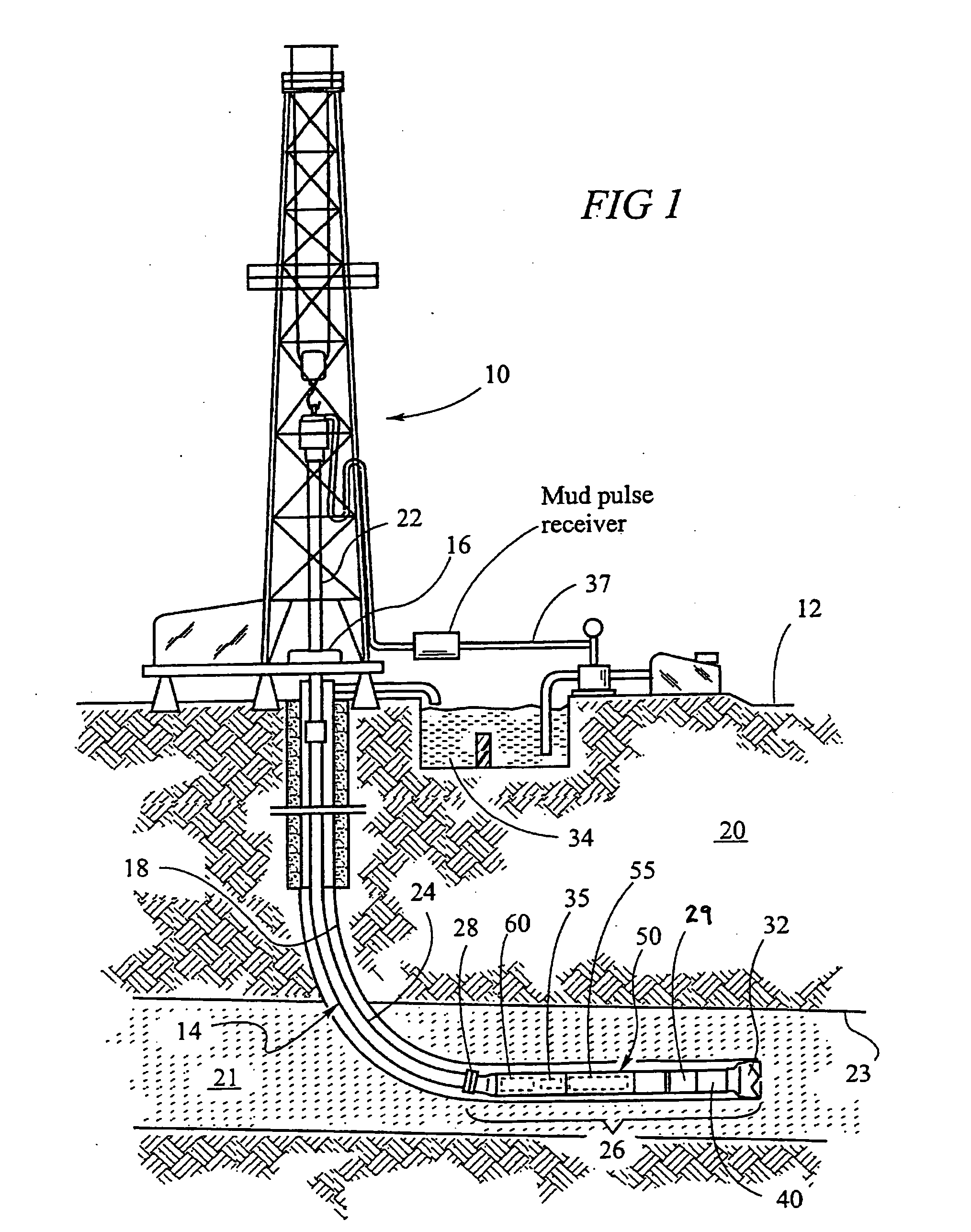
[0032]FIGS. 6A and 6B illustrate a resistivity tool design according to one embodiment of the invention. Referring to FIG. 6A, resistivity tool subassembly 602 is shown. The subassembly 602 is provided with one or more regions 606 of reduced diameter. A wire coil 604 is placed in the region 606 and spaced away from the surface of subassembly 602 by a constant distance. Coils 604 and 608 are transmitter coils and coils 610 and 612 are receiving coils. In operation, transmitter coil 604, 608 transmits an electromagnetic signal which propagates through the wellbore and surrounding formation. Receiver coils 610, 612 detect the electromagnetic signal and transmits it to the controller. A controller 622 may be located remotely from the receiver coils (such as inside a bottom hole assembly) and includes at least a microprocessor. A source of power is also necessary in the system.

[0033] A circuit card 614 may couple to transmitter coil 604 between its terminal ends, circuit card 616 may co...


PUM


Abstract

A resistivity tool includes receiver electronics near each receiver antenna loop. Placement of the electronics in this position such as at the circuit card between the terminal ends of the receiver antenna loop improves signal to noise ratio by reducing or eliminating interference, noise, and cross-talk of transmissions from the receiver to a remote microprocessor. By using material such as silicon-on-sapphire, electronics can be miniaturized and operate reliably at when exposed to high temperatures, even for long periods.

Description

CROSS-REFERENCE TO RELATED APPLICATIONS [0001] This application is a Nonprovisional application of U.S. application Ser. No. 60 / 520,992 filed Nov. 18, 2003, and entitled “High Temperature Electronics Suitable For Downhole Use” and U.S. application Ser. No. 60 / 520,950 filed Nov. 18, 2003, and entitled “High Temperature SIC Electronics Suitable For Downhole Use, High Temperature SIC Circuits, And Receiver SIC Electronics Proximate Antenna” which are incorporated herein by reference in their entirety.STATEMENT REGARDING FEDERALLY SPONSORED RESEARCH OR DEVELOPMENT [0002] Not Applicable. BACKGROUND OF THE INVENTION [0003] Modem petroleum drilling and production operations demand a great quantity of information relating to parameters and conditions downhole. Such information typically includes characteristics of the earth formations traversed by the borehole, along with data relating to the size and configuration of the borehole itself. The collection of information relating to conditions...

Claims


Application Information

Patent Timeline
IPC IPC(8): B81B7/00E21BE21B7/00E21B45/00G01VG01V3/08H01LH01L21/86H01L23/02H01L27/12H01Q
CPCB81B2207/115E21B47/0002H01L2924/13091H01L2224/73253H01L2224/73204H01L2224/32225H01L2224/16225E21B47/011H01L21/86H01L23/3157H01L27/12H01L2924/3011H01L2924/00G01V1/40E21B47/002E21B47/017E21B47/0175E21B47/00G01J3/00G01V8/00H01L21/70
Inventor FREEMAN, JAMES J.VEHRA, IMRANGOLLA, CHRISTOPHER A.SHARONOV, SERGEI
Owner HALLIBURTON ENERGY SERVICES INC
Learn More