Waveguide-based optical interferometer

Inactive Publication Date: 2005-08-04
LOCKHEED MARTIN CORP
View PDF20 Cites 7 Cited by
  • Summary
  • Abstract
  • Description
  • Claims
  • Application Information

AI Technical Summary

Benefits of technology

[0014] Many benefits are achieved by way of the present invention over conventional techniques. For example, certain embodiments of the present invention replaces many of the optical components, their mountings and mechanically variable paths in a conventional interferometer with photolithographically defined components in an inherently stable single mode planar optical waveguide circuit. The waveguide circuit is a planar lightwave circuit (PLC) fabricated in silica on silicon, for example, as described in M. Kawachi, Silica waveguides on silicon and their application to integrated-optic components, Optical and Quantum Electronics, Vol. 22, pp391-416 (1990). Other material systems may be used but PLC in si

Problems solved by technology

The major practical problem with high resolution interferometry is that changes of op

Method used


Image

  • Waveguide-based optical interferometer
  • Waveguide-based optical interferometer
  • Waveguide-based optical interferometer

Examples


Example

[0034] The present invention relates generally to interferometer techniques. More particularly, the invention provides a method and system for using waveguide in an interferometer. Merely by way of example, the invention has been applied to measuring spatial locations, but it would be recognized that the invention has a much broader range of applicability.

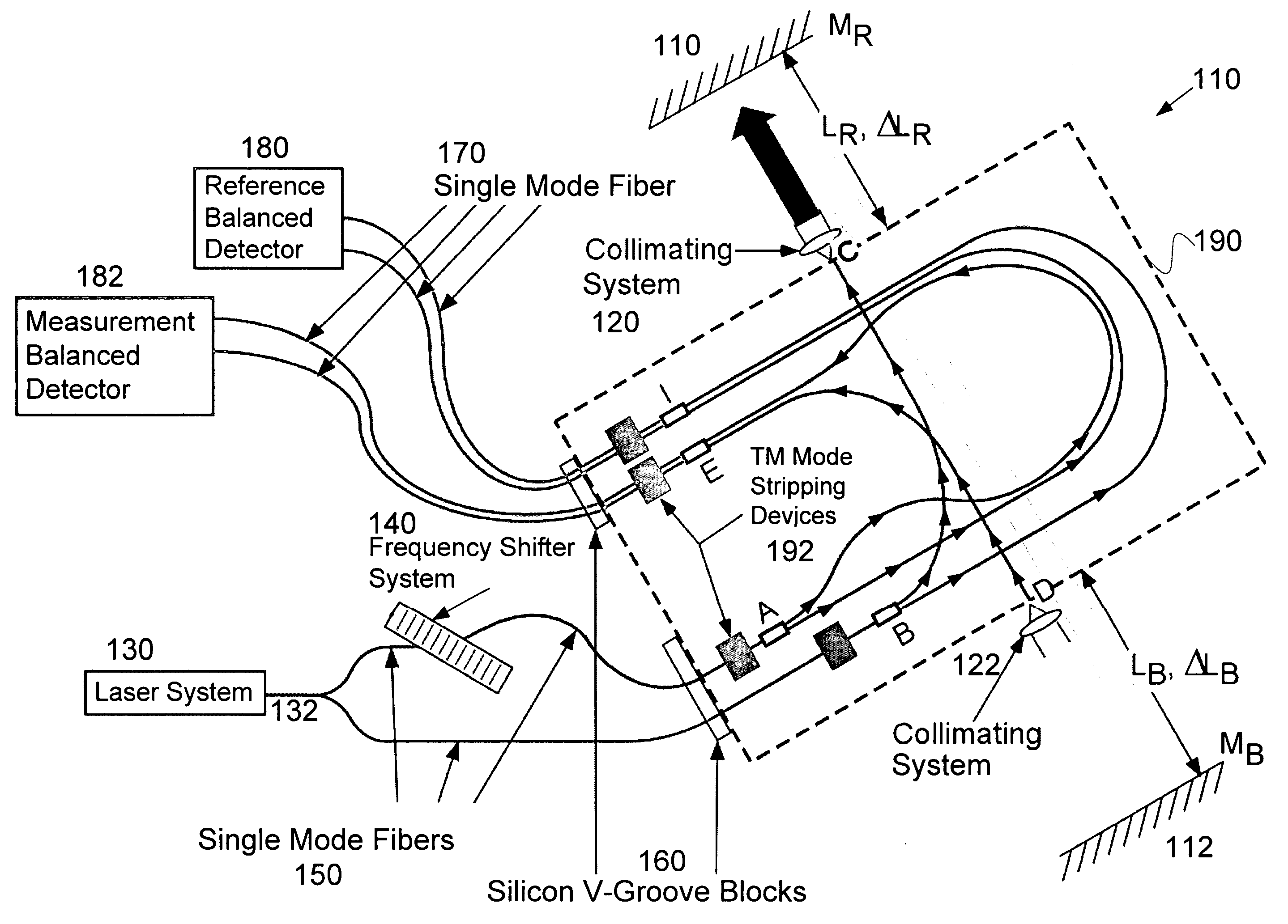
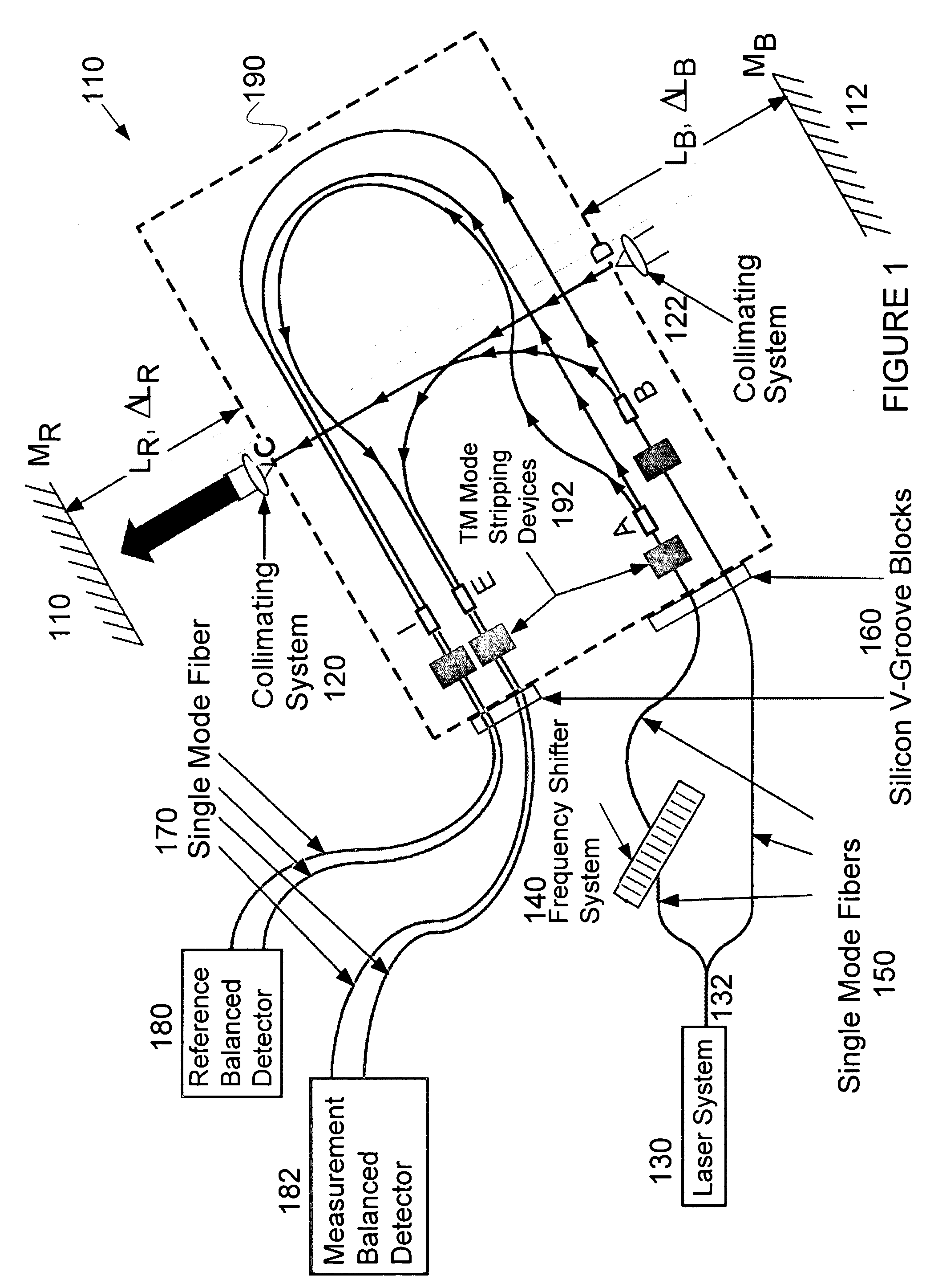
[0035] Certain embodiments of the present invention use a Planar Lightwave Circuit (PLC). For example, the embodiment shown in FIG. 1 uses a PLC. The circuit is also commonly referred to as a Photonic Integrated Circuit (PIC), a Lightwave Integrated Optic (LIO) circuit or an Integrated Optic (IO) circuit among other common nomenclatures in the literature. PLC fabrication technology has been developed in a number of material systems including glasses, polymers, lithium niobates and III-V semiconductors. Among the glasses are silica (SiO2) glasses with or without additional network forming oxides such as GeO2, TiO2, P2O5 and / or B2O3...


PUM


Abstract

Techniques for measuring spatial locations. An apparatus for measuring spatial locations includes a first object at a first location, a second object at a second location, and a waveguide-based interferometer coupled between the first object and the second object. The waveguide-based interferometer includes a waveguide material. The waveguide material is adapted to carry at least a reference beam and a measurement beam. The reference beam traverses a first path defined within the waveguide material. The measurement beam traverses a second path defined within the waveguide material and a third path defined outside of the waveguide material. The third path is related to at least one of the first location and the second location.

Description

CROSS-REFERENCES TO RELATED APPLICATIONS [0001] This application is a continuation-in-part application to U.S. application Ser. No. 10 / 051,122, which is incorporated by reference herein.STATEMENT AS TO RIGHTS TO INVENTIONS MADE UNDER FEDERALLY SPONSORED RESEARCH OR DEVELOPMENT [0002] NOT APPLICABLE REFERENCE TO A “SEQUENCE LISTING,” A TABLE, OR A COMPUTER PROGRAM LISTING APPENDIX SUBMITTED ON A COMPACT DISK. [0003] NOT APPLICABLE BACKGROUND OF THE INVENTION [0004] The present invention relates generally to interferometer techniques. More particularly, the invention provides a method and system for using waveguide in an interferometer. Merely by way of example, the invention has been applied to measuring spatial locations, but it would be recognized that the invention has a much broader range of applicability. [0005] Interferometers have been widely used for spatial measurements. The interferometers include homodyne interferometers, such as conventional Michelson interferometer, and ...

Claims


Application Information

Patent Timeline
IPC IPC(8): G01B9/02G01D5/353G02B6/125G02B6/14
CPCG01D5/35303G02B6/125G02B6/14G01B2290/60G01B9/02003G01B9/0207G01B9/02051
Inventor BELL, RAYMOND MARK JR.PERKINS, PATRICK ELLIOTTAMES, LAWRENCE LOWELLANDERSON, WILLIAM WALTER
Owner LOCKHEED MARTIN CORP
Why Eureka
Try Eureka