System and method of phase-locking a transmit clock signal phase with a receive clock signal phase

a technology of receive clock signal and transmit clock signal, which is applied in the direction of synchronising transmitters, code conversion, digital transmission, etc., can solve the problems of loss of data integrity, inability to run high-frequency lines between every receiver and transmitter, and large distance between

Active Publication Date: 2005-08-04
AVAGO TECH INT SALES PTE LTD
View PDF15 Cites 24 Cited by
  • Summary
  • Abstract
  • Description
  • Claims
  • Application Information

AI Technical Summary

Problems solved by technology

This frequency drift will eventually cause a loss of data integrity.
However, on today's large and complicated systems, it is not practical to run high-frequency lines between every receiver and transmitter.
Furthermore, although electronic components are very small, there is a relatively large distance between them.
It may not be feasible to maintain a common clock over such a distance.
For similar reasons, it may not be feasible to maintain direct clock-matching over such a distance.
When synchronizing a transmitter clock to a receiver clock, and jumping from one frequency to another frequency, instability of the system and loss of data integrity may occur on the analog side.

Method used


Image

  • System and method of phase-locking a transmit clock signal phase with a receive clock signal phase
  • System and method of phase-locking a transmit clock signal phase with a receive clock signal phase
  • System and method of phase-locking a transmit clock signal phase with a receive clock signal phase

Examples


Embodiment Construction

[0056] While the present invention is described herein with reference to illustrative embodiments for particular applications, it should be understood that the invention is not limited thereto. Those skilled in the art with access to the teachings provided herein will recognize additional modifications, applications, and embodiments within the scope thereof and additional fields in which the present invention would be of significant utility.

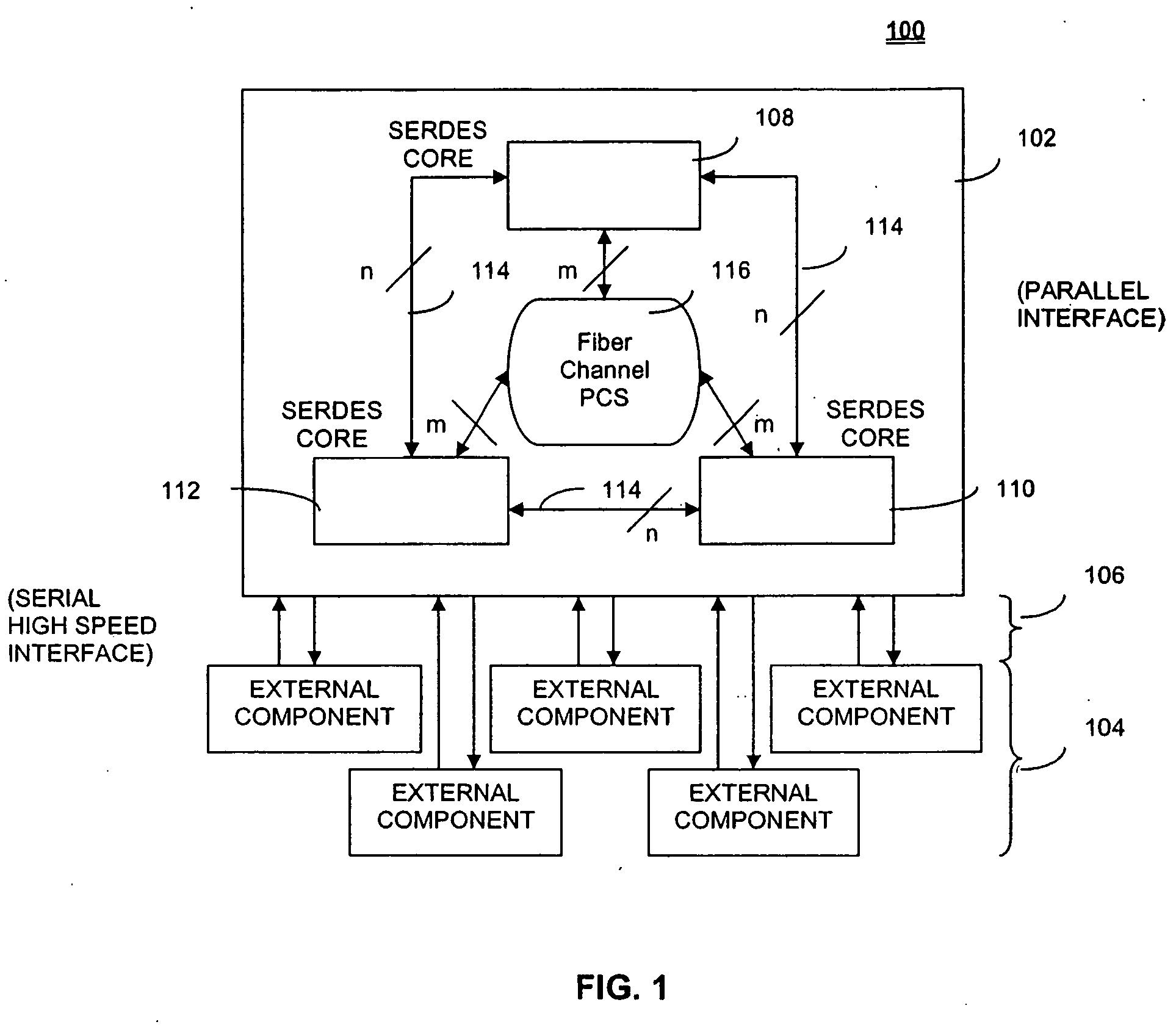
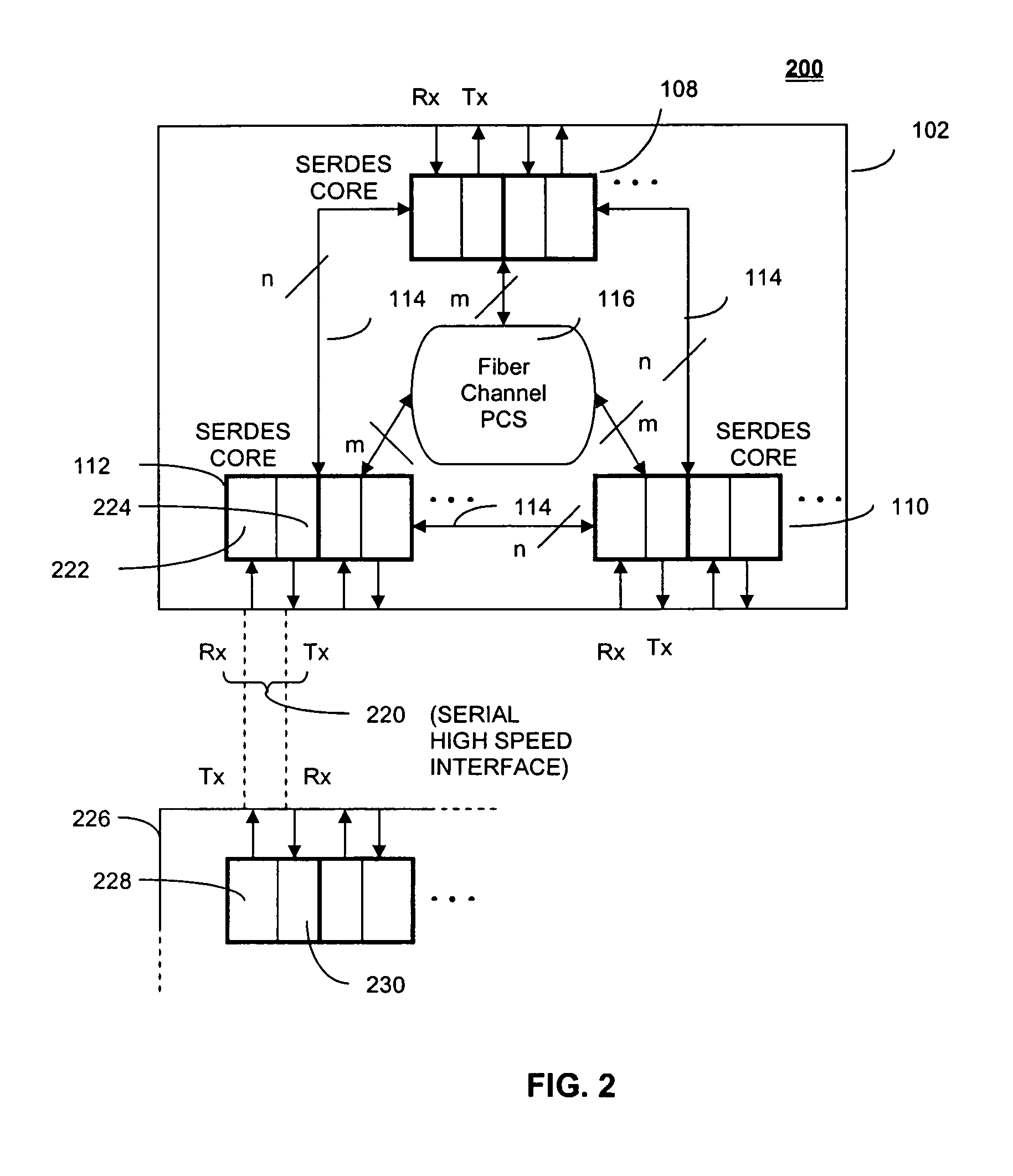
[0057]FIG. 1 illustrates an exemplary SERDES system 100, including a single SERDES chip 102 that communicates with a plurality of external components 104 through corresponding transmission and receive lines, serial high speed interface 106. External components 104 may include any combination of external devices such as disk drives or databases. SERDES chip 102 includes three SERDES cores 108, 110, 112. Each SERDES core can communicate with any other SERDES core, as indicated by lines 114. Fiber channel PCS 116 includes internal buses, control lo...


PUM


Abstract

Systems and methods for synchronizing a receive clock signal phase with a transmit clock signal phase are presented. A system includes a receiving channel and a transmitting channel, wherein the transmitting channel synchronizes a transmit clock signal phase with a receive clock signal phase based on receive clock signal phase data. A method includes storing a previous receive clock signal phase of a receiving channel and identifying a current receive clock signal phase of the receiving channel. The method further includes determining a phase difference between the previous receive clock signal phase and the current receive clock signal phase, and identifying a direction of the phase difference between the previous receive clock signal phase and the current receive clock signal phase. The method further includes adjusting a previous transmit clock signal phase of the transmitting channel to a current transmit clock signal phase of the transmitting channel based on the phase difference and direction.

Description

CROSS-REFERENCE TO RELATED APPLICATIONS [0001] This application claims the benefit of U.S. Provisional Application No. 60 / 540,295, filed Jan. 30, 2004, the contents of which is hereby incorporated by reference in its entirety.BACKGROUND OF THE INVENTION [0002] 1. Field of the Invention [0003] This invention relates generally to transceiver devices. More particularly, this invention relates to serializer / deserializer (SERDES) components of a transceiver device, and the phase-locking of a transmit clock signal phase with a receive clock signal phase. [0004] 2. Related Art [0005] A serializer / deserializer (SERDES) device converts received high-speed serial data into low-speed parallel data at a receiver. The parallel data may then be processed and then passed to a transmitter. At the transmitter, the low-speed parallel data is converted back into high-speed serial data for transmission out of the SERDES device. [0006] A SERDES device is used to control external devices, or used as a re...

Claims


Application Information

Patent Timeline
Patent Type & Authority Applications(United States)
IPC IPC(8): H03M9/00H04L7/00H04L25/00
CPCH03M9/00H04L7/0091H04L7/0079H04L7/0012
Inventor AMIRICHIMEH, ABBASBAUMER, HOWARDLOUIE, JOHNPARTHASARATHY, VASUDEVANYING, LINDA
Owner AVAGO TECH INT SALES PTE LTD
Why Eureka
Try Eureka