Bearing assembly and method for manufacturing the same

a technology of bearings and parts, applied in the direction of sliding contact bearings, connecting rod bearings, couplings, etc., can solve the problems of increased production costs, reduced allowable load, and difficult cutting, so as to improve reliability, reduce friction coefficient of bearing surfaces, and improve lubrication performance

Active Publication Date: 2005-08-04
DACC CARBON
View PDF3 Cites 20 Cited by
  • Summary
  • Abstract
  • Description
  • Claims
  • Application Information

AI Technical Summary

Benefits of technology

[0013] The second object of the present invention is to provide a bearing assembly in which a friction coefficient of a bearing surface is reduced to greatly improve reliability, and a method for manufacturing the same.
[0014] The third object of the present invention is to provide a bearing assembly in which lubrication performance is improved and the life of the bearing assembly can be assured by capturing hard particles generated due to wear, and a method for manufacturing the same.
[0015] The fourth object of the present invention is to provide a bearing assembly in which stress concentration on a bearing surface can be alleviated by forming a plurality of air channels capable of imparting directivity to an outer surface of a hemispherical bearing, and a method for manufacturing the same.
[0016] The fifth object of the present invention is to provide a bearing assembly that can be conveniently assembled to and disassembled from other parts, and a method for manufacturing the same.
[0017] The sixth object of the present invention is to provide a bearing assembly and a method for manufacturing the same, wherein a hemispherical bearing can be conveniently and accurately manufactured by means of near-net shape manufacturing of a bushing made of a fiber reinforced composite and a housing made of a material with superior thermal conductivity.
[0018] The seventh object of the present invention is to provide a bearing assembly in which adhesion and deterioration occurring between a spherical journal and a bearing surface due to radiation of frictional heat from a housing are prevented, thereby assuring the life thereof, and a method for manufacturing the same.

Problems solved by technology

However, such a conventional technique has a problem in that it is difficult to perform cutting due to severe tool wear.
Moreover, the conventional technique has a problem in that a processing rate cannot be increased due to damage to the strand prepreg, resulting in increased production costs.
In addition, the conventional technique has a problem in that an allowable load is lowered due to cracks generated in the hemispherical bearing 10.
In addition, the reinforcement fiber exhibits anisotropy in which friction coefficients in longitudinal and vertical directions differ from each other according to the kind thereof.
Accordingly, in the conventional hemispherical bearing 10, the moving direction of the spherical journal 20 cannot be coincident with the orientation of the reinforcement fibers, thereby causing a disadvantage in that the anisotropy of the reinforcement fibers in view of their wear properties cannot be sufficiently utilized.
Further, the formation of the air vent hole 14 at the center of the bearing surface 12 with greatest stress concentration has a potential problem in that a crack may be easily created from the periphery of the air vent hole 14.
The growth of such a crack causes breakage of the hemispherical bearing 10, greatly reducing its life and lowering its reliability.
In addition, there is a disadvantage in that hard particles or debris created due to wear of the spherical journal 20 and the hemispherical bearing 10 aggravate the wear phenomenon.

Method used


Image

  • Bearing assembly and method for manufacturing the same
  • Bearing assembly and method for manufacturing the same
  • Bearing assembly and method for manufacturing the same

Examples


first embodiment

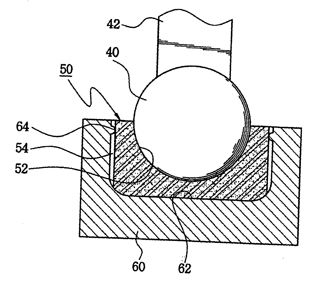
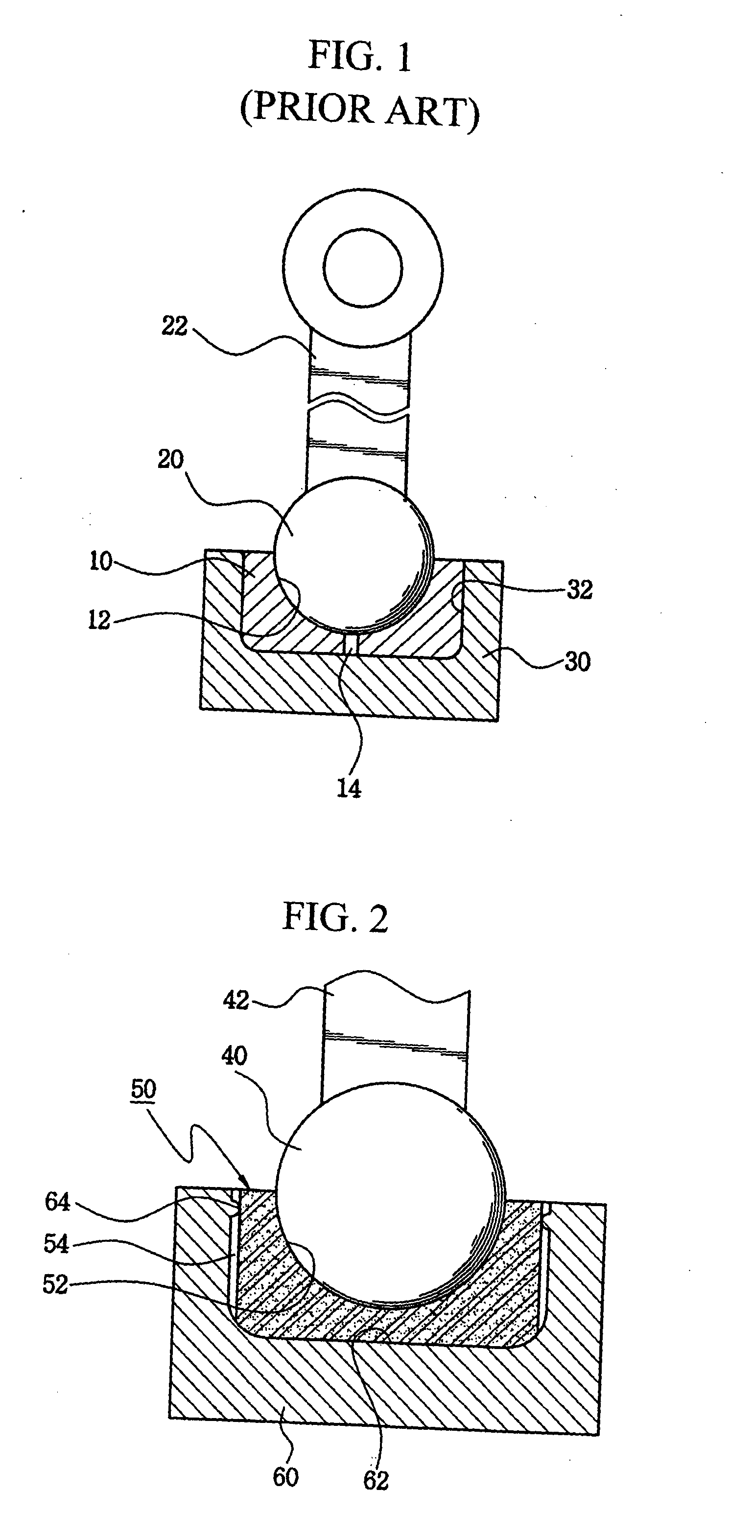
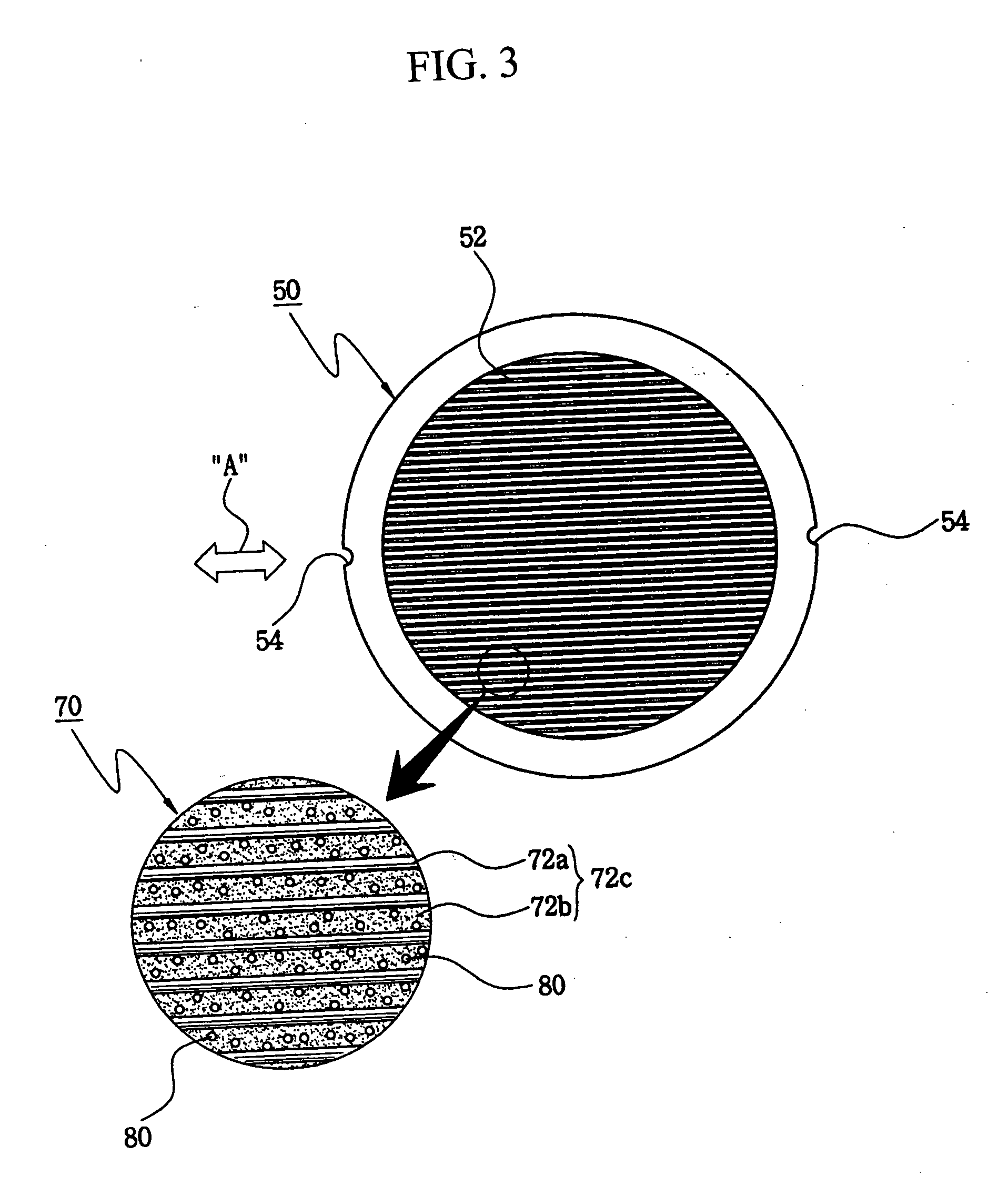
[0051] Referring to FIGS. 7A and 7B, in the bearing assembly of the first embodiment, the fiber reinforced composite 70 which is constructed by laminating the plurality of uni-directional prepregs 72 is subjected to hot compression molding to be used as the material for the hemispherical bearing 50. A mold set 90 used for the hot compression molding of the fiber reinforced composite 70 comprises a convex mold 92 and a concave mold 94. A core 96 for forming the air channels 54 of the hemispherical bearing 50 is provided on an inner surface of the concave mold 94.

[0052] Referring to FIGS. 5, 6 and 7A, the fiber reinforced composite 70 is supplied between the convex mold 92 and the concave mold 94 of the mold set 90 to perform the hot compression molding of the fiber reinforced composite 70. The thermoplastic resin particles 80 or self-lubrication particles 84 are uniformly distributed on the surface of the uppermost layered unidirectional prepreg 72c of the fiber reinforced composite ...

second embodiment

[0057] As shown in FIGS. 11 and 13, the fiber reinforced composite 270 comprises a uni-directional prepreg 272, a plurality of woven fabric prepregs 274 and staple-fiber prepregs 276. Each of the uni-directional prepreg 272 and the woven fabric prepregs 274 comprises reinforcement fibers 272a and 274a and matrixes 272b and 274b in the same manner as the uni-directional prepreg 172 and the woven fabric prepreg 174 in the second embodiment, respectively. Generally, the staple-fiber prepregs 276 can be manufactured by a process that is simpler than the process for manufacturing the uni-directional prepreg 272 and the woven fabric prepregs 274, and have an advantage in that production costs can be reduced.

[0058] Meanwhile, in the fiber reinforced composite 270, the uni-directional prepreg 272 is arranged as an uppermost layer, and a lowermost layered woven fabric prepreg 274c with the same structure as the woven fabric prepreg 274 is arranged as a lowermost layer. Further, the plurality...

fourth embodiment

[0061]FIGS. 16A and 16B show variations of the bearing assembly according to the present invention. As shown in FIG. 16A, the bushing 330 is fixedly mounted in the recess 342 of the housing 340. An end portion of the bushing 330 is formed as a bent section 334 that covers an upper surface of the housing 340. The bent section 334 of the bushing 330 causes the connecting rod 42 not to come into direct contact with the housing 340, so that wear of the connecting rod 42 and the housing 340 can be prevented. Further, the connecting rod 42 is prevented from coming into contact with an end surface of the bushing 330, thereby avoiding interlaminar peeling in the fiber reinforced composite 370.

[0062] As shown in FIG. 16B, a flat section 336 is formed at an upper portion of an outer surface of the bushing 330. The flat section 336 of the bushing 330 is brought into close contact with a flat section 346 formed at an upper portion of the recess 342. Reinforcement fibers of the fiber reinforced ...


PUM


Abstract

The present invention discloses a bearing assembly capable of assuring mechanical strength and reducing a friction coefficient and stress concentration, and a method for manufacturing the same. The present invention comprises a spherical journal and a hemispherical bearing that is made of a fiber reinforced composite and has a bearing surface for establishing a spherical pair with the spherical journal. The fiber reinforced composite can be constructed by arranging a uni-directional prepreg, woven fiber prepregs and staple-fiber prepregs in a variety of configurations, and thermoplastic resin particles or self-lubrication particles are uniformly provided on the bearing surface. It is possible to alleviate stress concentration generated on the bearing surface by forming a plurality of air channels capable of imparting directivity on an outer surface of the hemispherical bearing.

Description

BACKGROUND OF THE INVENTION [0001] 1. Field of the Invention [0002] The present invention relates to a bearing assembly and a method for manufacturing the same, and more particularly, to a bearing assembly in which a fiber reinforced composite (FRC) is used to secure mechanical strength as well as to reduce a friction coefficient and stress concentration, thereby improving reliability, and a method for manufacturing the same. [0003] 2. Description of the Background Art [0004] A hemispherical bearing is a mechanical element that supports a spherical journal and is used in a variety of machines and apparatuses. The spherical journal and the hemispherical bearing are used as a ball joint for connecting two components to allow free movement of the two components. In the case of a ball joint, the hemispherical bearing is called a “housing socket” and the spherical journal is called a “ball stud.”[0005] The structure of a bearing assembly into which a conventional spherical journal and a ...

Claims


Application Information

Patent Timeline
Patent Type & Authority Applications(United States)
IPC IPC(8): F16C9/04F16C11/06F16C23/04F16C25/04F16C33/20F16J1/22
CPCF16C9/04F16C11/0633Y10T403/32631F16J1/22F16C33/201
Inventor LEE, DAI GILPARK, DONG CHANGLEE, SEONG MINKIM, BYUNG CHULKIM, HAK SUNGKIM, SUNG SUKIM, JONG WOON
Owner DACC CARBON
Why Eureka
Try Eureka