Optical transmission device

a transmission device and optical technology, applied in the field of optical transmission devices, can solve the problems of erroneous detection of side-peak noise, wrong connection, and over-1,000,000 per unit, and achieve the effect of improving the quality and reliability of oadm function, and allowing the configuration of highly flexible and economical oadm networks

Inactive Publication Date: 2005-08-04
FUJITSU LTD
View PDF4 Cites 26 Cited by
  • Summary
  • Abstract
  • Description
  • Claims
  • Application Information

AI Technical Summary

Benefits of technology

[0019] The present invention was created in view of the above circumstances, and an object thereof is to provide an optical transmission device

Problems solved by technology

Thus, in the conventional wavelength selection by means of an AOTF, the number of wavelength peaks is counted to detect a desired wavelength, and accordingly, there is a possibility that noise such as a side-peak is erroneously detected as a wavelength signal.
If a side-peak is regarded as a substantial peak, then it is not possible to connect with a target node, giving rise to a problem that connection is established with a wrong node different from the target node, for example.
However, the device uses the combination of a diffraction grating for wavelength dispersion and a PD array and thus is costly (over ¥1,000,000 per unit) as well as large-sized (170×220×28 mm).
Accordingly, the device is not applicable to nodes which need to be reduced in cost and size, such as those used in a metropolitan area network or an access network.
H09-18421), on the other hand, when a loopback test is performed, the communication path is cut off because of the switching of the optical switch, and therefore, it is not possible to conduct the continuity test on a specific wavelength only.
With the conventional technique, the communication line itself is switched by the optical switch, so that all the wavelengths λ1 to λ8 are redirected back, giving rise to a problem that the communic

Method used


Image

  • Optical transmission device
  • Optical transmission device
  • Optical transmission device

Examples


Embodiment Construction

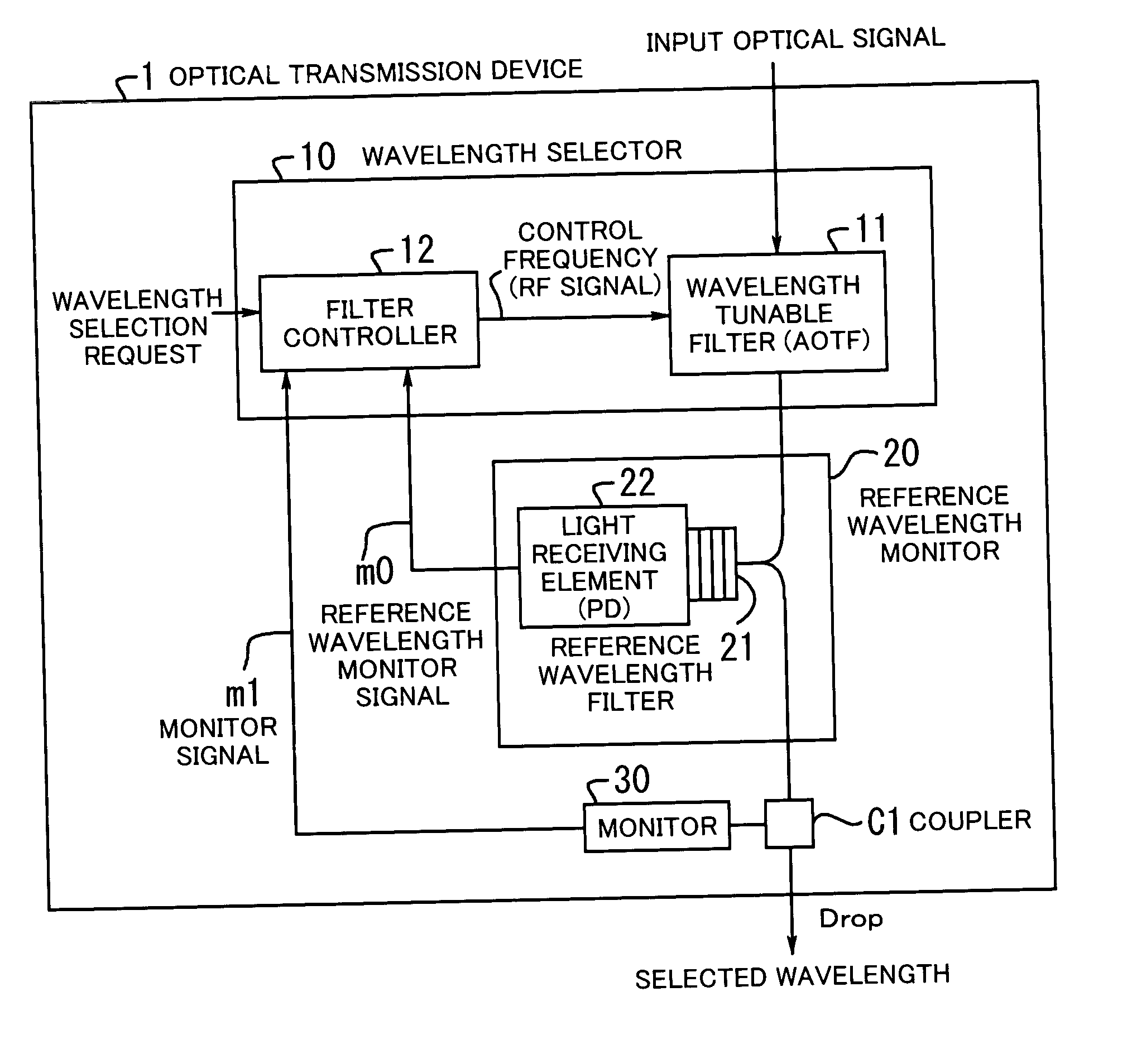
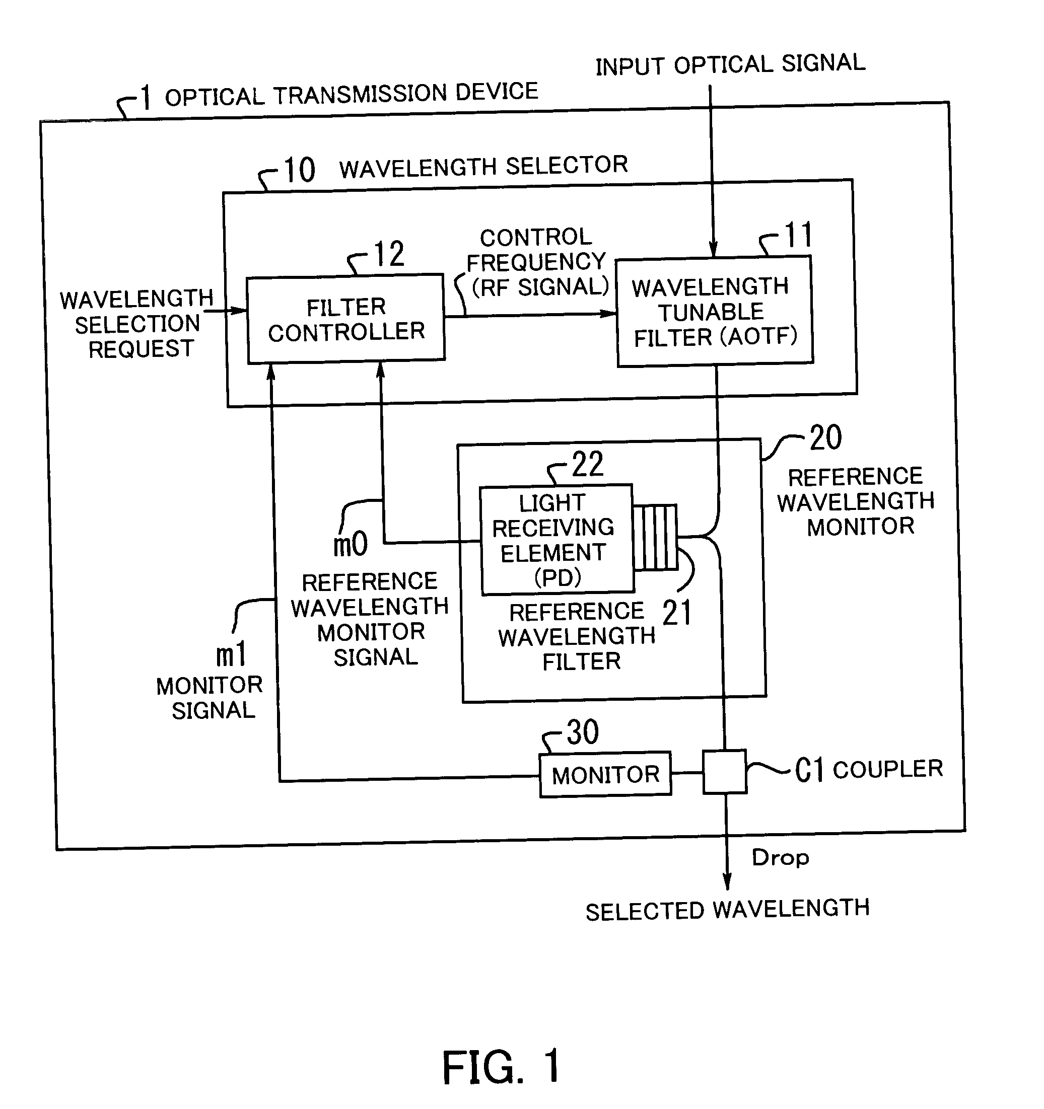
[0058] Preferred embodiments of the present invention will be described below with reference to the accompanying drawings. FIG. 1 illustrates the principle of an optical transmission device according to the present invention. The optical transmission device 1 comprises a wavelength selector 10, a reference wavelength monitor 20 and a monitor 30, and transmits an optical WDM signal.

[0059] The wavelength selector 10 includes a wavelength tunable filter 11 and a filter controller 12. The wavelength tunable filter (hereinafter AOTF) 11 variably selects a wavelength in accordance with a control frequency (RF signal frequency).

[0060] The filter controller 12 applies an RF signal to the AOTF 11 while scanning wavelength over an entire signal bandwidth. Based on a reference wavelength monitor signal m0 then received, the filter controller detects a reference control frequency (hereinafter reference RF) which permits the AOTF 11 to select a reference wavelength and in accordance with which...


PUM


Abstract

An optical transmission device improved in quality and reliability of OADM function and permitting configuration of highly-flexible, economical OADM networks. A wavelength tunable filter variably selects a wavelength according to a control frequency. A filter controller applies the control frequency to the filter while scanning wavelength over an entire signal bandwidth, to detect, from a reference wavelength monitor signal supplied thereto, a reference control frequency which permits the filter to select a reference wavelength and according to which wavelength is matched. On receiving a wavelength selection request, the controller obtains a target control frequency from the reference control frequency and the position of a target wavelength relative to the reference wavelength, and applies the obtained frequency to the filter. A reference wavelength filter transmits the reference wavelength therethrough. A light-receiving element monitors the transmitted reference wavelength to generate the monitor signal.

Description

[0001] This application is a continuing application, filed under 35 U.S.C. §111(a), of International Application PCT / JP2003 / 004793, filed Apr. 15, 2003. BACKGROUND OF THE INVENTION [0002] 1. Field of the Invention [0003] The present invention relates to optical transmission devices, and more particularly, to an optical transmission device for transmitting an optical WDM (Wavelength Division Multiplex) signal. [0004] 2. Description of the Related Art [0005] As a result of an explosively increasing demand for data communications chiefly via the Internet traffic, backbone networks are required to have larger capacity and to cover even longer distances. Also, because of diversification of services that users make use of, there has been a demand for networks which have high reliability and flexibility and yet are economical. [0006] Especially, optical communication networks form the basis of the infrastructure of information communication networks. Thus, optical communication networks ar...

Claims


Application Information

Patent Timeline
IPC IPC(8): G02F1/125H04B10/27H01L31/12H01S5/0687H04B10/07H04B10/275H04B10/29H04J14/00H04J14/02
CPCH04B10/572H04J14/0204H04J14/0209H04J14/0227H04J14/0213H04J14/022H04J14/021H04J14/0201
Inventor NAKAGAWA, GOJIMIYATA, HIDEYUKIKAI, YUTAKAONAKA, HIROSHIYOSHIDA, SETSUOSONE, KYOSUKEUENO, TOMOHIRO
Owner FUJITSU LTD
Why Eureka
Try Eureka