
Electronic drill depth indicator

a technology of depth indicators and drills, which is applied in the field of drills, can solve the problems of inherently unreliable devices and difficult assembly in a standardized fashion, and achieve the effect of convenient installation and calibration

Inactive Publication Date: 2005-08-04
ATLAS COPCO DRILLING SOLUTIONS
View PDF27 Cites 59 Cited by
  • Summary
  • Abstract
  • Description
  • Claims
  • Application Information

AI Technical Summary

Benefits of technology

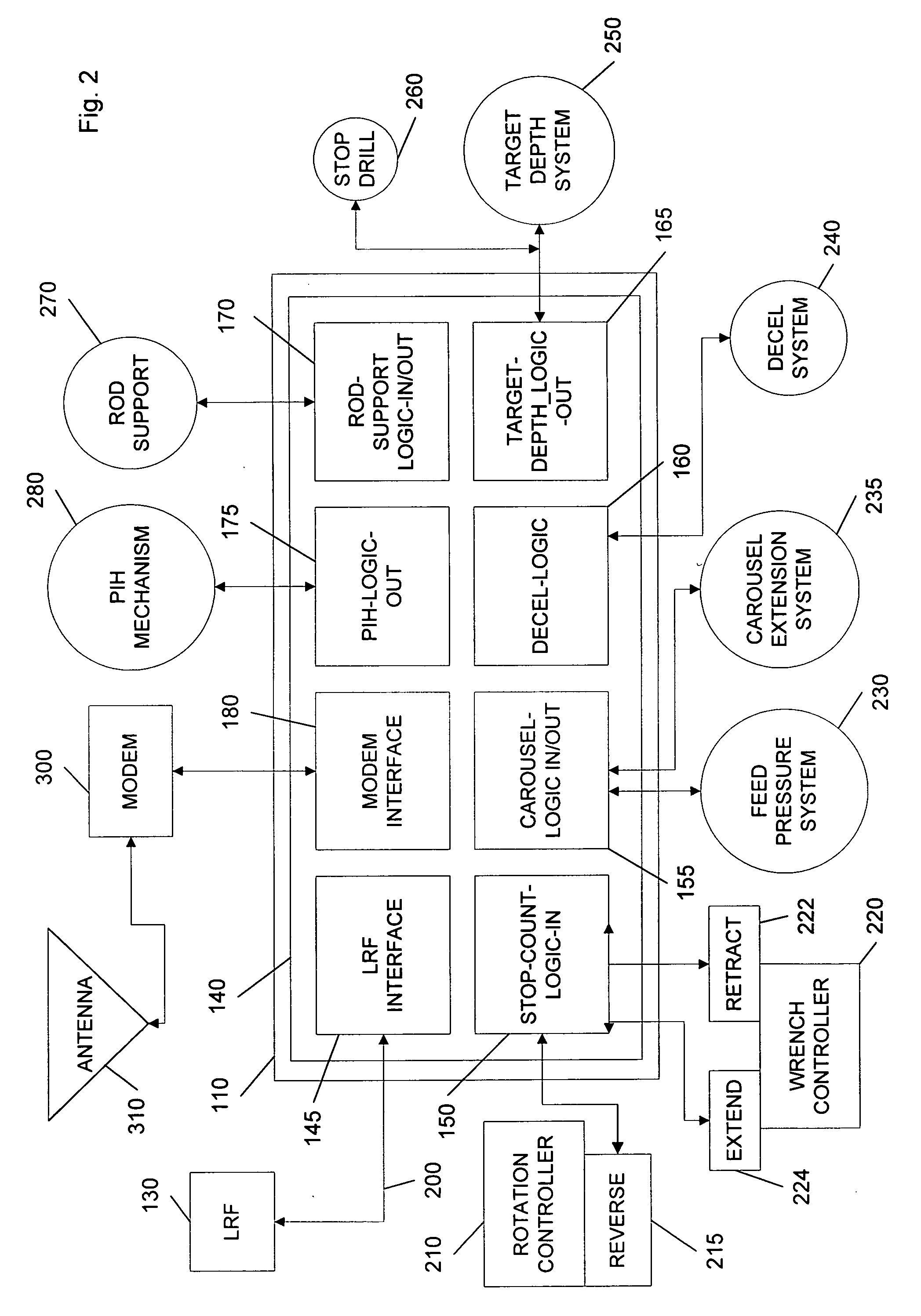
[0006] Some embodiments of the invention can be designed in a manner for ease of integration into existing and new machines. Some other embodiments of the invention can be sold as an easily installed and calibrated after-market product. Still other embodiments of the present invention can be integrated into a complete control system for a new product, such as a drilling machine. In other embodiments, the invention can be a plug-in module to a preexisting control system.

Problems solved by technology

The encoder is driven mechanically by a rotating function of the feed system, These devices are inherently unreliable and they are difficult to assemble in a standardized fashion onto drilling machines because drilling machine feed systems can take a variety of forms.

Method used


Image

  • Electronic drill depth indicator
  • Electronic drill depth indicator
  • Electronic drill depth indicator

Examples


Embodiment Construction

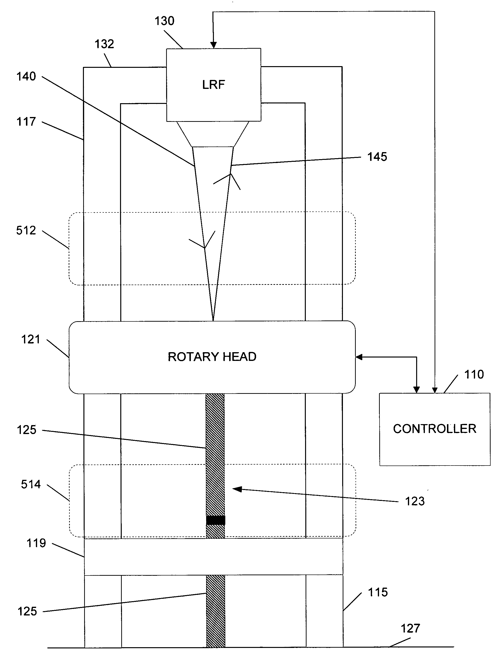
[0018] Before embodiments of the invention are described, it is to be understood that the invention is not limited in its application to the details of construction and the arrangement of components set forth in the following description or illustrated in the drawings. The invention is capable of other embodiments and of being practiced or of being carried out in various ways. Also, it is to be understood that the phraseology and terminology used herein is for the purpose of description and should not be regarded as limiting. The use of “including,”“comprising,” or “having” and variations thereof herein is meant to encompass the items listed thereafter and equivalents thereof as well as additional items. Unless limited otherwise, the terms “connected,”“coupled,” and “mounted,” and variations thereof herein are used broadly and encompass direct and indirect connections, couplings, and mountings. In addition, the terms “connected” and “coupled” and variations thereof are not restricte...


PUM

PropertyMeasurementUnit
distanceaaaaaaaaaa
distanceaaaaaaaaaa
timeaaaaaaaaaa

Abstract

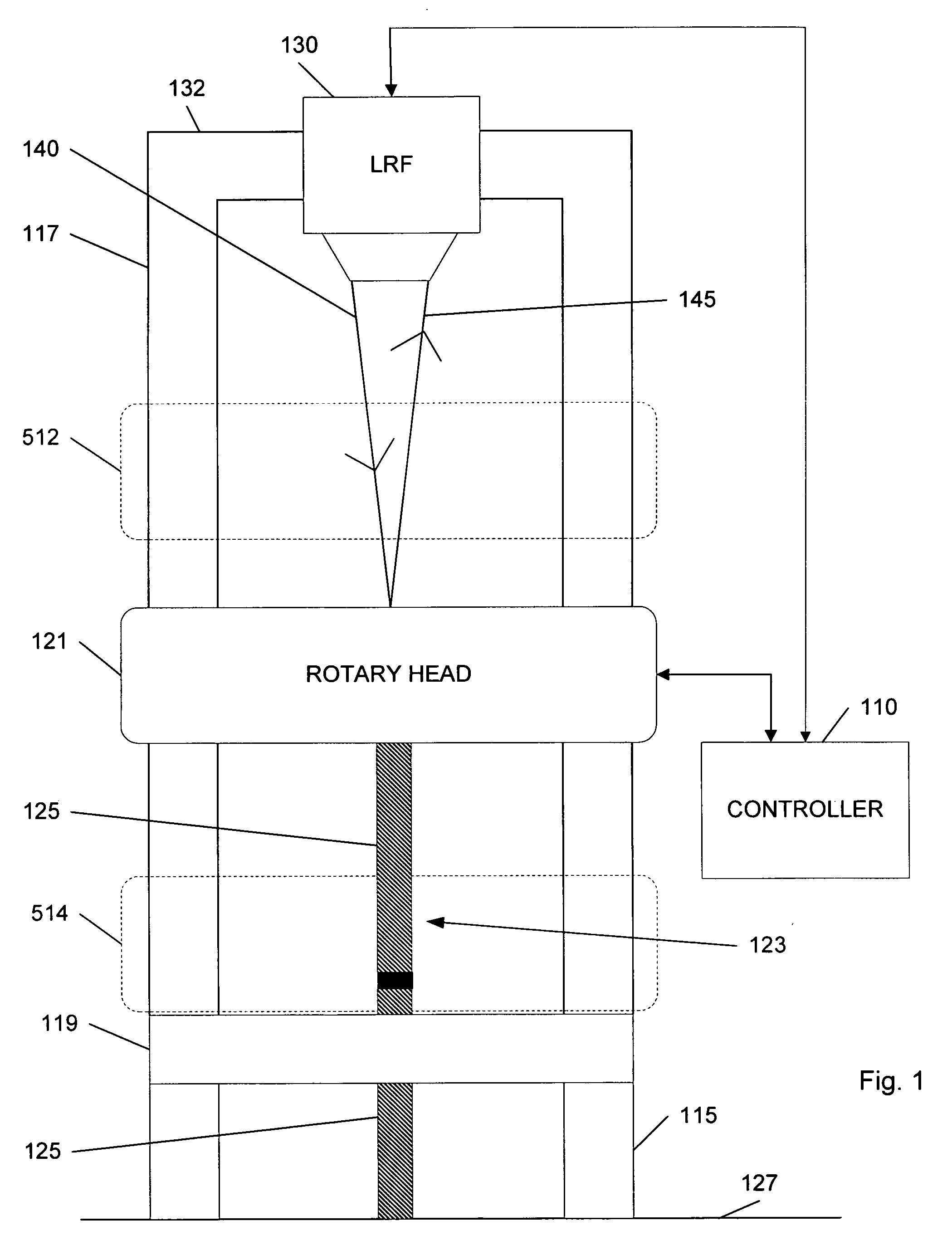
A system for determining a depth of a hole drilled by a drilling machine. The system can include a drill string including one or more drill rods, wherein each of the one or more drill rods has a length; a target; a laser range finder configured to determine a plurality of distance readings, wherein each of the plurality of distance readings includes a distance value between the laser range finder and the target; and a controller configured to obtain the plurality of distance readings from the laser range finder. The controller processes the plurality of distance readings to produce a calculated distance between the laser range finder and the target. The controller may also use the calculated distance and the length of each of the one or more drill rods included in the drill string to determine the depth of the hole drilled by the drilling machine.

Description

RELATED APPLICATIONS [0001] The present application claims priority to U.S. provisional patent application Ser. No. 60 / 541,903 titled “ELECTRONIC DRILL DEPTH INDICATOR,” filed on Feb. 3, 2004.FIELD OF THE INVENTION [0002] The invention relates to drilling machines, and more particularly, to drilling machines having electronic drill depth indicators. BACKGROUND OF THE INVENTION [0003] Drilling machines typically have a frame, a deck, a tower, and a rotary head. The frame is supported for movement over the ground, and the tower is mounted on the frame. The deck is supported by the frame and has a generally horizontal upper surface with an opening through which a drill rod is extendable. The rotary head moves along the tower and engages with a drill rod. When the drill rod is engaged with the rotary head, the drill rod rotates with the rotary head. A feed system can control the movement of the rotary head along the tower. The feed system can force the rotary head downward to cause the ...

Claims


Application Information

Patent Timeline
Patent Type & Authority Applications(United States)
IPC IPC(8): B23B39/06B23B49/00E21B47/04G01C3/02
CPCB23B49/00B23B2260/0487B23B2260/092Y10T408/175B23B2270/54E21B47/04Y10T408/21B23B2260/128
Inventor FIELD, GRANT ANDREW
Owner ATLAS COPCO DRILLING SOLUTIONS
Learn More