Gun drill guide and gun drill guide assembly

a gun drill and guide assembly technology, applied in the direction of turning machine accessories, manufacturing tools, transportation and packaging, etc., can solve the problems of only one cutting edge of the gun drill, insufficient diameter or structure of the f′ to hold it in place, and inability to overcome whipping, bowing and vibration fully, etc., to achieve the effect of improving the gun drill operation

Active Publication Date: 2005-08-04
F J FEDDERSEN
View PDF7 Cites 14 Cited by
  • Summary
  • Abstract
  • Description
  • Claims
  • Application Information

AI Technical Summary

Benefits of technology

[0011] A primary object of the invention is to provide a gun drill guide which is held securely in place during the drilling operation and which provides improved gun drilling operation, including controlling the whipping, bowing and vibration of the gun drill.
[0012] A further primary object of the invention is to provide a gun drill guide assembly which provides increased wear and durability and decreases the vibration of the gun drill.
[0013] A further primary object of the invention is to provide a gun drill guide assembly which includes a chip deflector assembly to provide protection to the bearing and the drill guide, to control the whipping of the drill, to secure the drill guide in place, and to increase the rate of production through more efficient operation.

Problems solved by technology

However, such whipping, bowing and vibration cannot fully be overcome with a gun drill having only one cutting edge because the drill shaft is off balance and not on the center of gravity.
F′ is not of sufficient diameter or structure to hold it in place.
This is necessarily detrimental and affects the efficiency and quality of the gun drilling operation and increases the expense of operation.
In practice, such guides also have a tendency to pop out of the bearing when the drill is operated at high rpms.
The tendency of a gun drill to whip, bow and vibrate is particularly a problem with smaller drill sizes such as one-quarter inch or smaller.
This movement of the gun drill adversely affects the quality and efficiency of the gun drilling operation.
When using prior art guides at such higher RPMs, this generates even more bearing heat which results in the guide getting even hotter, thereby softening the guide and causing the guide to pop out of the bearing even more frequently.
These chip deflectors have a tendency to get stuck on the drill shaft because chips get stuck behind it or the plastic seal gets damaged, all of which requires manual removal and down time of the machine.
Also, when the chip deflector gets stuck on the shaft, the chip deflector moves forward with the drill shaft toward the workpiece causing the chips to clog the hole in the workpiece.
As previously stated, the prior art chip deflectors get stuck and move forward on the shaft causing chips to build up in the drilled hole.
Such build-up affects the cooling lubricant pressure since higher pressure is required to push the chips out of the drill hole.
This is particularly problematic when drilling deep holes and requires higher lubricant pressure.
In practice, this is not used extensively or at all due to the extra step, difficulty and expense in molding this type of drill guide.

Method used


Image

  • Gun drill guide and gun drill guide assembly
  • Gun drill guide and gun drill guide assembly
  • Gun drill guide and gun drill guide assembly

Examples


Embodiment Construction

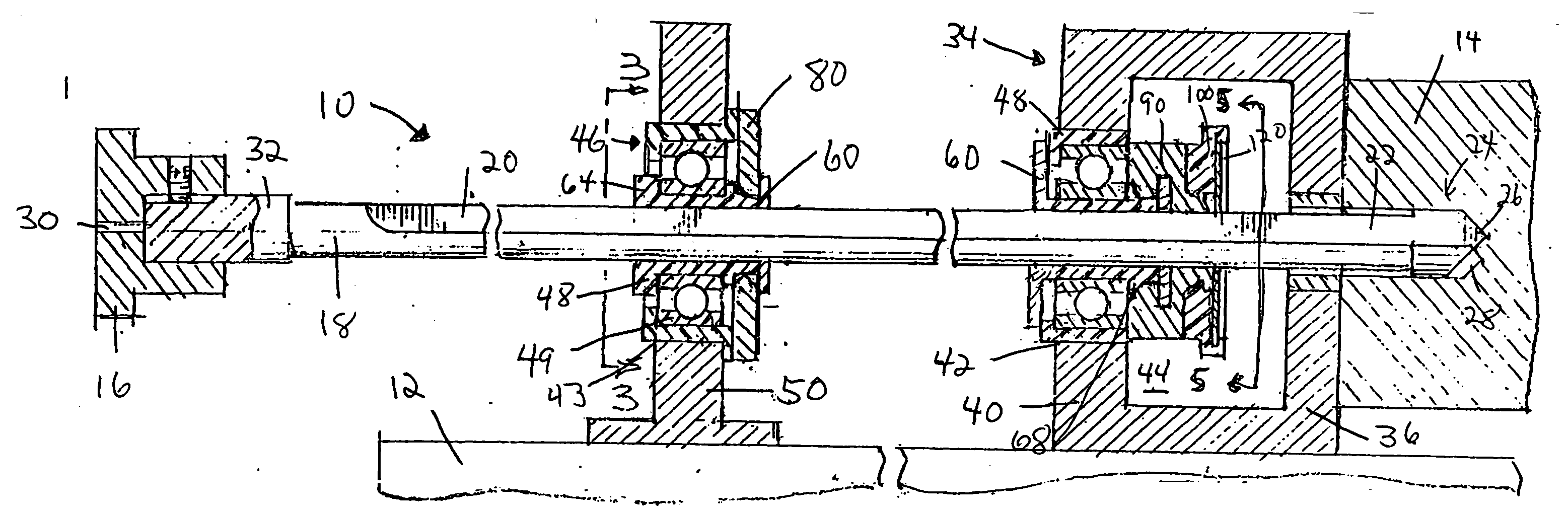
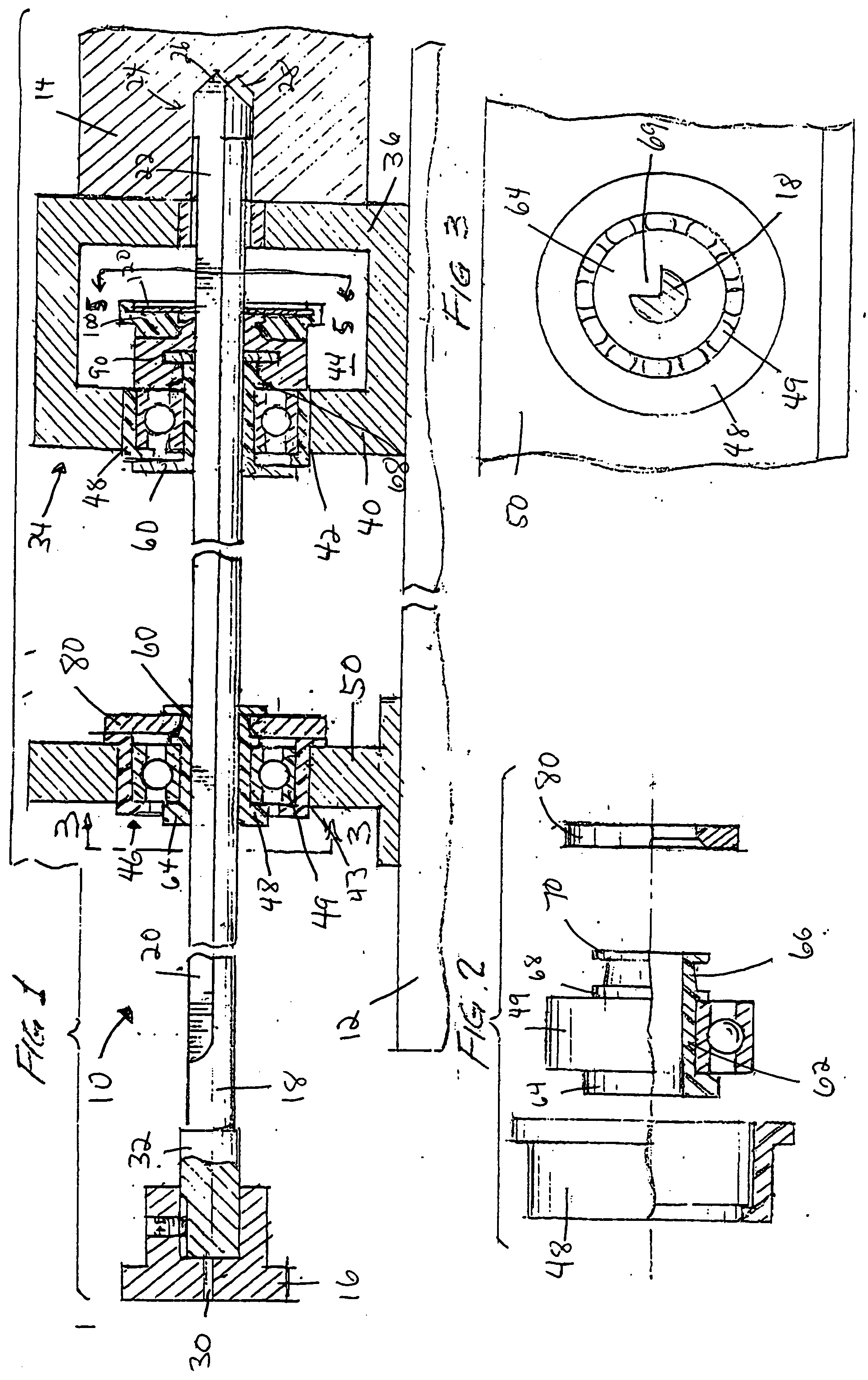
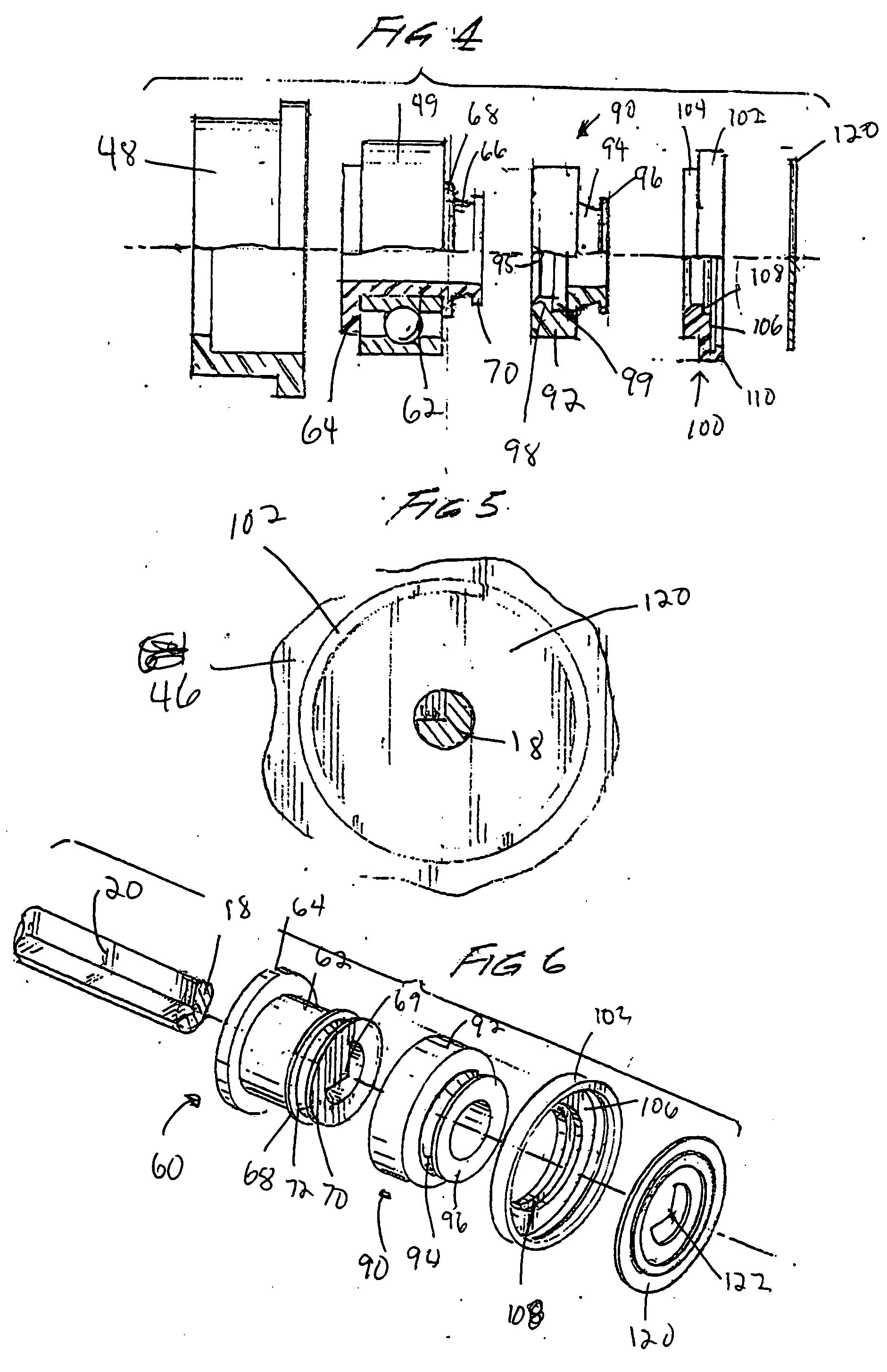
[0041] An improved gun drill guide and gun drill guide assembly are shown in FIGS. 1 through 17. Referring to FIG. 1, a representative gun drill apparatus 10 is shown for purposes of illustrating the guide of the invention. It is understood that the drill guide and drill guide assembly of the invention can be used in operations other than gun drilling and the inventions disclosed herein are not limited to gun drilling. Rather, the term “gun drilling” is used generically for drilling apparatus for making deep holes and using an extended drill shaft. For example, the inventions are useful in the auto industry for, among other things, drilling steering columns; the medical industry for drilling medical parts; the motorcycle industry for drilling axles; the oil industry for drilling shafts; the military for drilling pins for tanks, etc.

[0042] The gun drilling apparatus 10 is secured to a drilling apparatus 12 providing for various cutting operations to be conducted on a metal workpiece...


PUM

PropertyMeasurementUnit
widthaaaaaaaaaa
diameteraaaaaaaaaa
hardnessaaaaaaaaaa

Abstract

A gun drill guide is disclosed comprising a cylinder body member of a resilient polymer material having a central opening extending therethrough, a radially extending flange means at one end thereof to engage the end face of a bearing assembly and an annular groove near the opposite end thereof defined by second and third radially extending flanges for engaging the opposite end face of the bearing assembly. A locking member, a chip deflector assembly, a stabilizer assembly or other guide attachment are disclosed which may be attached to the drill guide.

Description

FIELD OF INVENTION [0001] This invention relates to a gun drill guide and gun drill guide assembly. More specifically, the invention relates to a gun drill guide and gun drill guide assembly which reduces the whipping, vibration and bowing of the drill. The gun drill guide and assembly provide a means for keeping the guide from popping out of a bearing and provide a means to secure a chip deflector in a chip box to deflect chips and lubricant. The gun drill guide and assembly provide for more efficient operation of the gun drill and will, consequently, save substantial time and expense in the drilling of gun barrels and other materials. BACKGROUND OF THE INVENTION [0002] Gun drill guides are well known in the art. They are used to help prevent the tendency of the drill shaft to whip, bow and vibrate when the drill is operated at relatively high rpms. However, such whipping, bowing and vibration cannot fully be overcome with a gun drill having only one cutting edge because the drill ...

Claims


Application Information

Patent Timeline
Patent Type & Authority Applications(United States)
IPC IPC(8): B23B41/02B23B47/34
CPCB23B41/02B23B2226/33B23B2250/16B23B2251/424Y10T408/50Y10S408/705Y10T408/569Y10T408/567B23B2270/30B23B51/066
Inventor FEDDERSEN, FREDERICK J.
Owner F J FEDDERSEN
Why Eureka
Try Eureka