Robust carbon monolith having hierarchical porosity

a carbon monolith and hierarchical porosity technology, applied in ceramics, other domestic objects, chemical processes, etc., can solve the problems of poor electrical conductivity of conventional beds packed with porous graphite particles, lack of robust stationary phases for high-performance liquid chromatography, etc., and achieve the effect of superior hydrodynamic properties of a monolithic structur

Inactive Publication Date: 2005-08-04
UNIV OF TENNESSEE RES FOUND +1
View PDF3 Cites 121 Cited by
  • Summary
  • Abstract
  • Description
  • Claims
  • Application Information

AI Technical Summary

Benefits of technology

[0007] Accordingly, objects of the present invention include provision of: a robust carbon monolith having hierarchical porosity; a robust carbon monolith characterized by macropores and mesopores; a monolithic column for HPLC that can be used in a wide range of chemical environments and at elevated temperatures; a highly conductive monolithic column for HPLC; a method of synthesis of a porous carbon monolith; use of any of the foregoing as a versatile HPLC column bed; use of any of the foregoing as a highly conductive EMLC column; and a robust material that is characterized by a combination of chemical merits of a high specific surface area carbon adsorbent and superior hydrodynamic properties of a monolithic structure. Further and other objects of the present invention will become apparent from the description contained herein.

Problems solved by technology

Firstly, there is a lack of robust stationary phases for high performance liquid chromatography (HPLC) that provide broadly useful retention and separation patterns.
Moreover, although polymeric phases are not as pH-limited, they are often degraded rapidly when used with certain common organic solvents and / or at high temperatures.
Conventional beds packed with porous graphite particles suffer from a poor electrical conductivity, hence from a heterogeneous distribution of the electric charges of the particles.
The electrical equilibrium of the column can only be achieved after washing it for a very long time with the mobile phase.
This causes a slow adjustment of the experimental conditions and the waste of valuable chemicals.
The development of EMLC has been considerably slowed down by the lack of a suitable stationary phase.
Carbon monoliths made thereby take the shape of the voids (pores) of the template and are of very low density and are not structurally robust.

Method used


Image

  • Robust carbon monolith having hierarchical porosity
  • Robust carbon monolith having hierarchical porosity
  • Robust carbon monolith having hierarchical porosity

Examples


example i

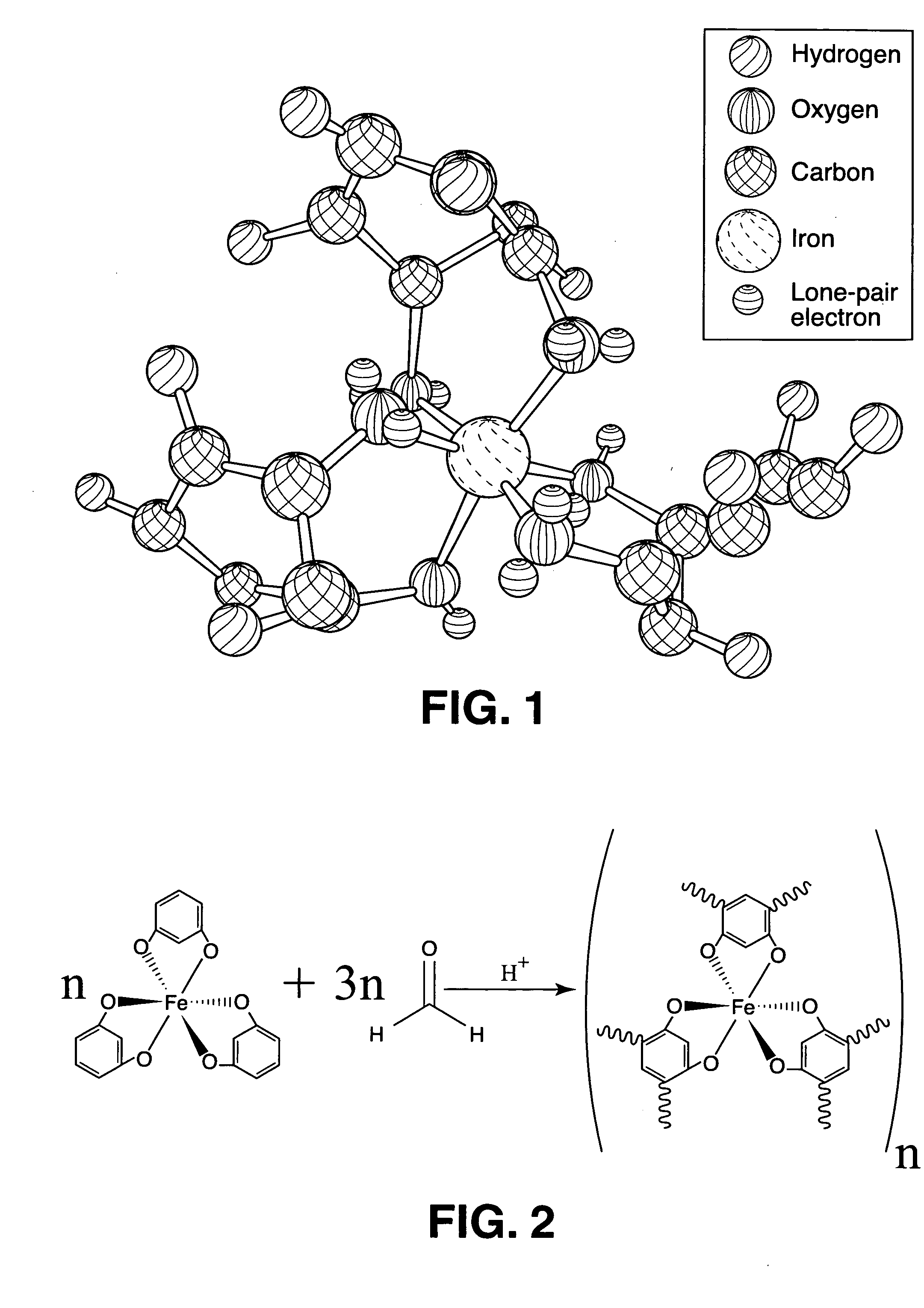
[0056] 6 g of silica beads were dispersed in 5 g of an aqueous solution of ethanol (80% ethanol, 20% water) using an ultrasonic mixer. 1.08 g FeCl3 was then dissolved into the suspension, followed with 2.2 g of resorcinol, dissolved by hand shaking. The colloid solution turned dark immediately after the addition of resorcinol, indicating the formation of a resorcinol / Fe(III) complex. 2.4 g of an ice-cooled, 37% formaldehyde solution in water was introduced into this mixture, in one step, with hand shaking. The mixture was kept in an ice-water bath for 10 minutes with magnetic stirring. After removal of the ice-water bath, the mixture was slowly transferred into 5 mm ID glass tubes which were capped when filled. These tubes were then placed in a 70° C. water bath. The mixture polymerized rapidly into a solid rod inside the glass tube. This rod detached from the tube wall because of the shrinking caused by polymerization. The polymer rod was aged time period of 5 h in the glass tube, ...

example ii

[0062] Generally following the method of Example I, 2 g of silica beads having a particle size of 5 μm and 1 g of silica beads having a particle size of 13 nm were used. Following introduction of the formaldehyde solution, the colloid was centrifuged at about 3000 RPM for 30 min. Only the large particles form a compacted ordered colloidal array while the small particles remain as a stable suspension between them. After removal of the supernant, poly-condensation of the colloidal array into a rod was carried out in the centrifuge tube in an oven at 50° C.

[0063] Method 4: Fe Catalyzed Polymer with a Duplex Template of Polystyrene Beads

[0064] This method is essentially the same as Method 3 above, the only difference being that polystyrene beads replace the silica beads.

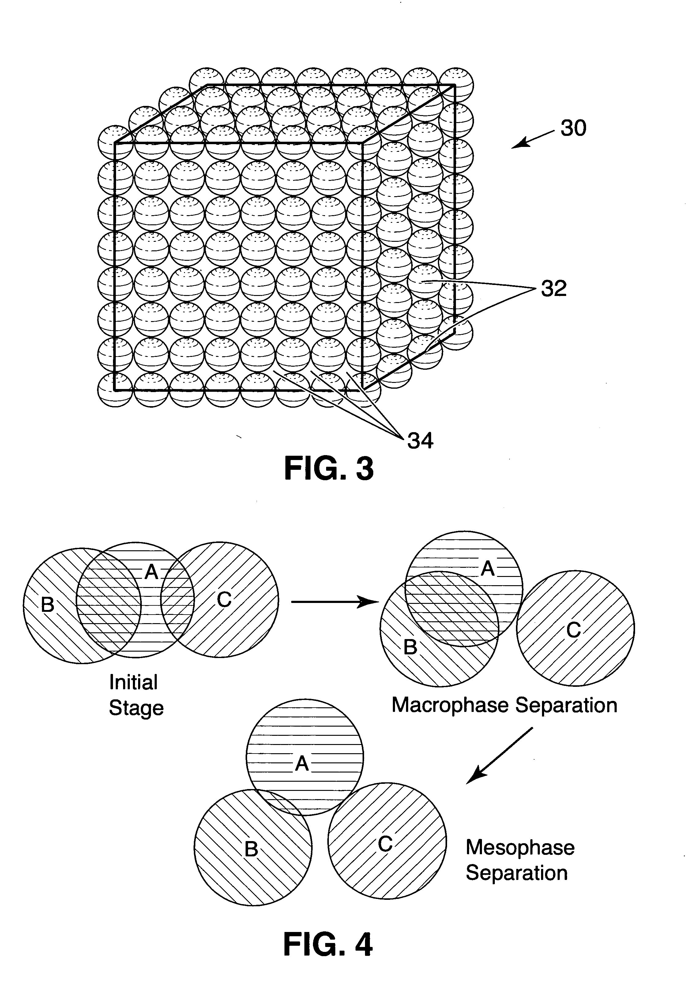
[0065] For a better understanding of the above described colloidal templating methods, FIG. 3 illustrates the fabrication of the precursor monoliths made via methods 1 to 4. The colloidal array 30 can be silica and / or...

example iii

[0068] 10.4 g of TEOS, 8.7 g P123 and 3.5 g 1 m HCl were mixed in 69 g ethanol. The mixture reacted at 70° C. for 1.5 h. 3.3 g resorcinol in 3.6 g 37% formaldehyde was added into the mixture after the removal of ethanol by vacuum. The final mixture was introduced into a glass tube and reacted at 80° C. for 4 h. Afterwards the rod was thoroughly dried in a vacuum oven at 100° C.

[0069] Method 6: Reaction Induced Dual Phase Separation of Ternary Organic Mixture

[0070] A homogeneous solution of component A, component B, and component C is induced to perform dual phase separation via reaction. The polymerization of component A induces a primary phase separation of polymerized component A and component C in micron or submicron scale. As component A polymerizes, component B becomes enriched in the polymerized phase of component A. With further polymerization of component A, component B separates from component A, resulting in a secondary, nanometer scale phase separation. The removal of c...


PUM

PropertyMeasurementUnit
sizeaaaaaaaaaa
sizeaaaaaaaaaa
sizeaaaaaaaaaa

Abstract

A carbon monolith includes a robust carbon monolith characterized by a skeleton size of at least 100 nm, and a hierarchical pore structure having macropores and mesopores.

Description

[0001] The United States Government has rights in this invention pursuant to contract no. DE-AC05-00OR22725 between the United States Department of Energy and UT-Battelle, LLC.FIELD OF THE INVENTION [0002] The present invention relates to carbon monoliths having hierarchical porosity, and more particularly to robust carbon monoliths characterized by macropores and mesopores. BACKGROUND OF THE INVENTION [0003] The invention addresses two different and independent difficulties in the art of liquid chromatography. [0004] Firstly, there is a lack of robust stationary phases for high performance liquid chromatography (HPLC) that provide broadly useful retention and separation patterns. Benefiting from the superior hydraulic and mass transfer kinetic properties of a monolithic structure, a variety of monolithic columns have been developed for fast separations during the last few years. These well known monolithic columns are categorized in to two general groups: silica-based columns and p...

Claims


Application Information

Patent Timeline
Patent Type & Authority Applications(United States)
IPC IPC(8): B01J20/20B01J20/28B01J20/282C01B31/00C04B35/52C04B38/00C04B38/04C04B38/06
CPCB01J20/20C01B31/02B01J20/28042B01J20/28078B01J20/28083B01J20/28085B01J20/282B01J2220/82C01B31/00C04B38/045C04B38/0615B01J20/28004C04B35/52C04B38/0022C04B38/0064C01B32/00C01B32/05
Inventor DAI, SHENGGUIOCHON, GEORGES A.LIANG, CHENGDU
Owner UNIV OF TENNESSEE RES FOUND
Why Eureka
Try Eureka