
Phosphors spray and method for spraying the same

a technology of phosphors and spraying methods, applied in the direction of coatings, tubes with screens, electric discharge tubes, etc., can solve the problems of high cost and low light intensity of methods, and achieve the effect of reducing light intensity, evenly controlling thickness, and complicated gradients

Inactive Publication Date: 2005-08-04
TECO NANOTECH CO LTD
View PDF6 Cites 3 Cited by
  • Summary
  • Abstract
  • Description
  • Claims
  • Application Information

AI Technical Summary

Benefits of technology

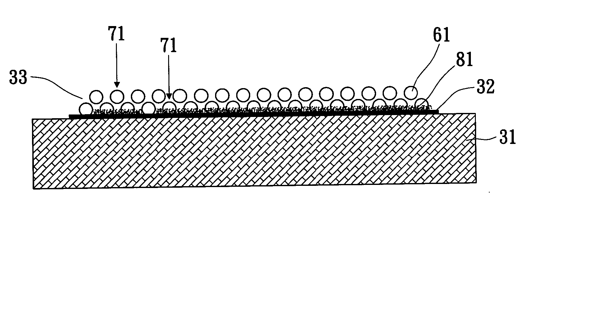
[0008] According to the conventional methods for the phosphors layers of the FED mentioned above, the coating is difficult to coat evenly, the lighting efficiency thereof decreases due to a large quantity of phosphors layers, the method should be equipped with apparatuses with multiple steps, or the method provides complicated gradients that are expensive. The present invention should conquer the difficulties mentioned above. The present invention provides a phosphors-spraying method for evenly controlling the thickness thereof. The present invention also provides a phosphors-spraying method with an even thickness thereof for a low electric field or a low voltage. The present invention further provides a spray adopted to a phosphors-spraying method to coat the same on an anode glass substrate. The present invention still further provides a spray with phosphors having a conductivity to avoid electric charges accumulating to affect a lighting efficiency thereof. Finally, the present invention provides a spray with simple gradient to reduce costs.
[0010] The secondary object of the invention is therefore to specify a phosphors-spraying method to reduce the amount of phosphors layers and to increase denseness ability between the phosphors to improve the lighting efficiency.
[0011] The third object of the invention is therefore to specify a phosphors spray adopted to a phosphors-spraying method with improved adhesion abilities to coat the same on an anode glass substrate or a positive electric layer.
[0012] The fourth object of the invention is therefore to specify a phosphors spray adopted to a phosphors-spraying method to reduce a resistance of phosphors layers and avoid electric charges accumulating to affect a lighting efficiency of a FED.
[0013] The fifth object of the invention is therefore to specify a phosphors spray adopted to a phosphors-spraying method to reduce manufacturing and material costs for business applications.
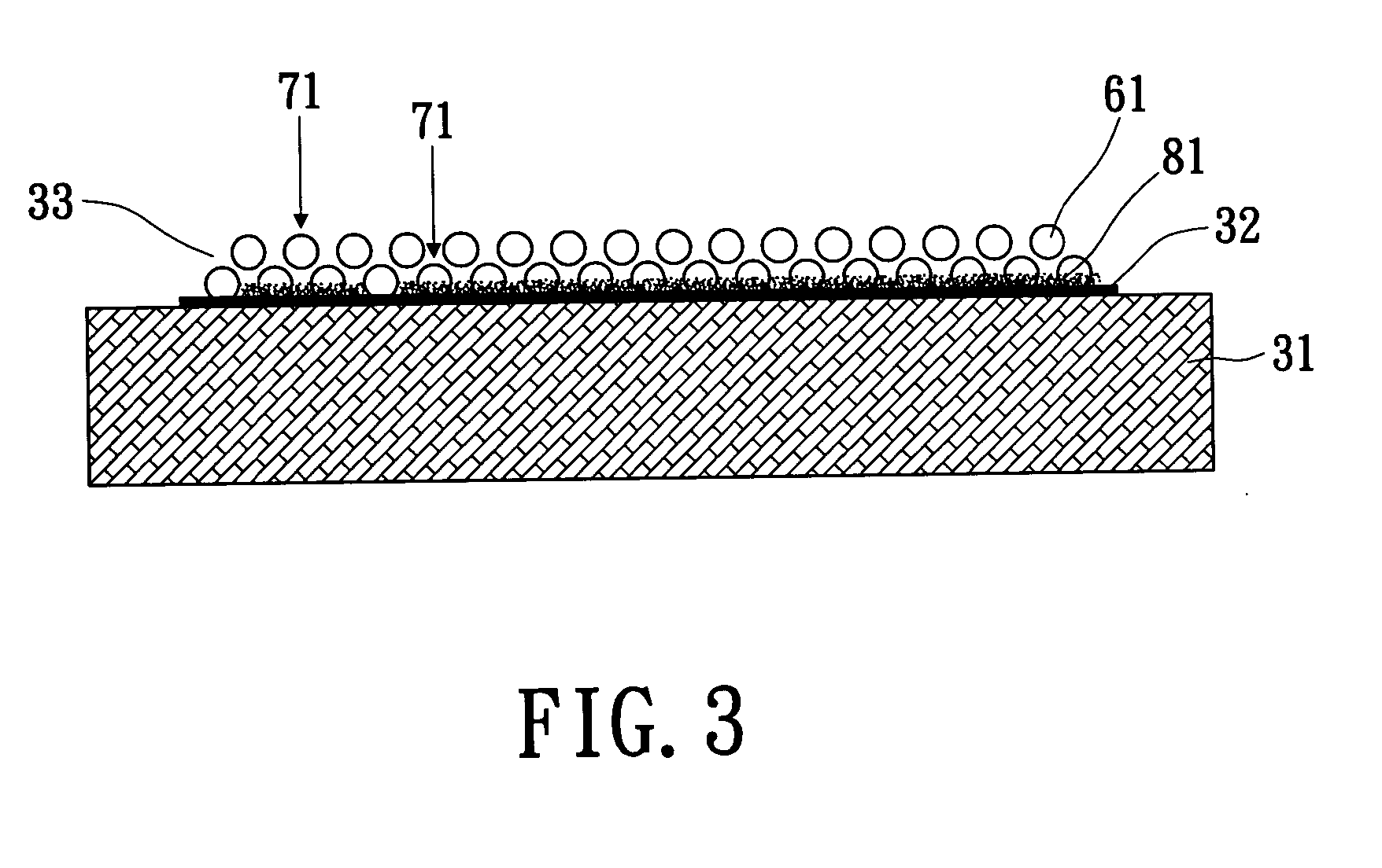
[0014] According to the invention, this object is achieved by a method for spraying a phosphors spray to get a phosphors layer. A proper and vaporizable solvent is selected to disperse and suspend the phosphors scattered therein. The phosphors is mixed with a binder, an electrical powder and a surfactant to be the spray with a low viscosity. The mixed solvent is carried by pressurized air to spray uniformly on a positive conductive layer or a positive glass substrate. A thickness of a film sprayed by the mixed solvent can be adjusted and controlled by a spraying frequency thereof to control evenly and uniformly the thickness thereof in the spraying. The mixed solvent then vaporizes rapidly to expose the phosphors on a surface of the film, and by means of pressurized air, particles of phosphors can be evenly sprayed on the anode conductive layer or the anode glass substrate to improve adhesion abilities thereof, the phosphors layer can be triggered via a low electric field or a low voltage thereby for improving the lighting efficiency of a FED.

Problems solved by technology

According to the conventional methods for the phosphors layers of the FED mentioned above, the coating is difficult to coat evenly, the lighting efficiency thereof decreases due to a large quantity of phosphors layers, the method should be equipped with apparatuses with multiple steps, or the method provides complicated gradients that are expensive.

Method used


Image

  • Phosphors spray and method for spraying the same
  • Phosphors spray and method for spraying the same
  • Phosphors spray and method for spraying the same

Examples


Embodiment Construction

[0022] The present invention provides a method for spraying a phosphors spray to obtain a phosphors layer. A proper and vaporizable solvent is selected to disperse and suspend the phosphors scattered therein. The phosphors is mixed with a binder, an electrical powder, or a surfactant to be the phosphors spray with a low viscosity. The mixed solvent is propelled by a pressurized air to be sprayed uniformly on an anode conductive layer or an anode glass substrate. A thickness of the film sprayed by the mixed solvent can be adjusted and controlled by a spraying frequency thereof to control evenly and uniformly the thickness thereof in the spraying. The mixed solvent then vaporizes rapidly to expose the phosphors on a surface of the film, and according to the pressurized air, particles of phosphors can be evenly sprayed on the anode conductive layer or the anode glass substrate to improve adhesion abilities thereof. The phosphors layer can be triggered via a low electric field or a low ...


PUM

PropertyMeasurementUnit
diameteraaaaaaaaaa
diameteraaaaaaaaaa
thicknessaaaaaaaaaa

Abstract

A phosphors spray and a method for spraying the phosphors spray to get a phosphors layer are provided. The phosphors spray and the method are characterized as: 1. A thickness of a phosphors layer can be controlled and adjusted uniformly by a phosphors spraying process. 2. The phosphors layer is thin and easy to manufacture, and further is suitable for a low electrical field or a low voltage within a FED. 3. The phosphors layer has high adhesion abilities to coat on a positive glass substrate or a positive electric layer of the FED, and a low resistance thereof to avoid electric charges accumulating to affect a lighting efficiency of a FED. 4. A solvent of the present invention simplifies the gradients thereof to diminish the costs thereof and practice into commercial use.

Description

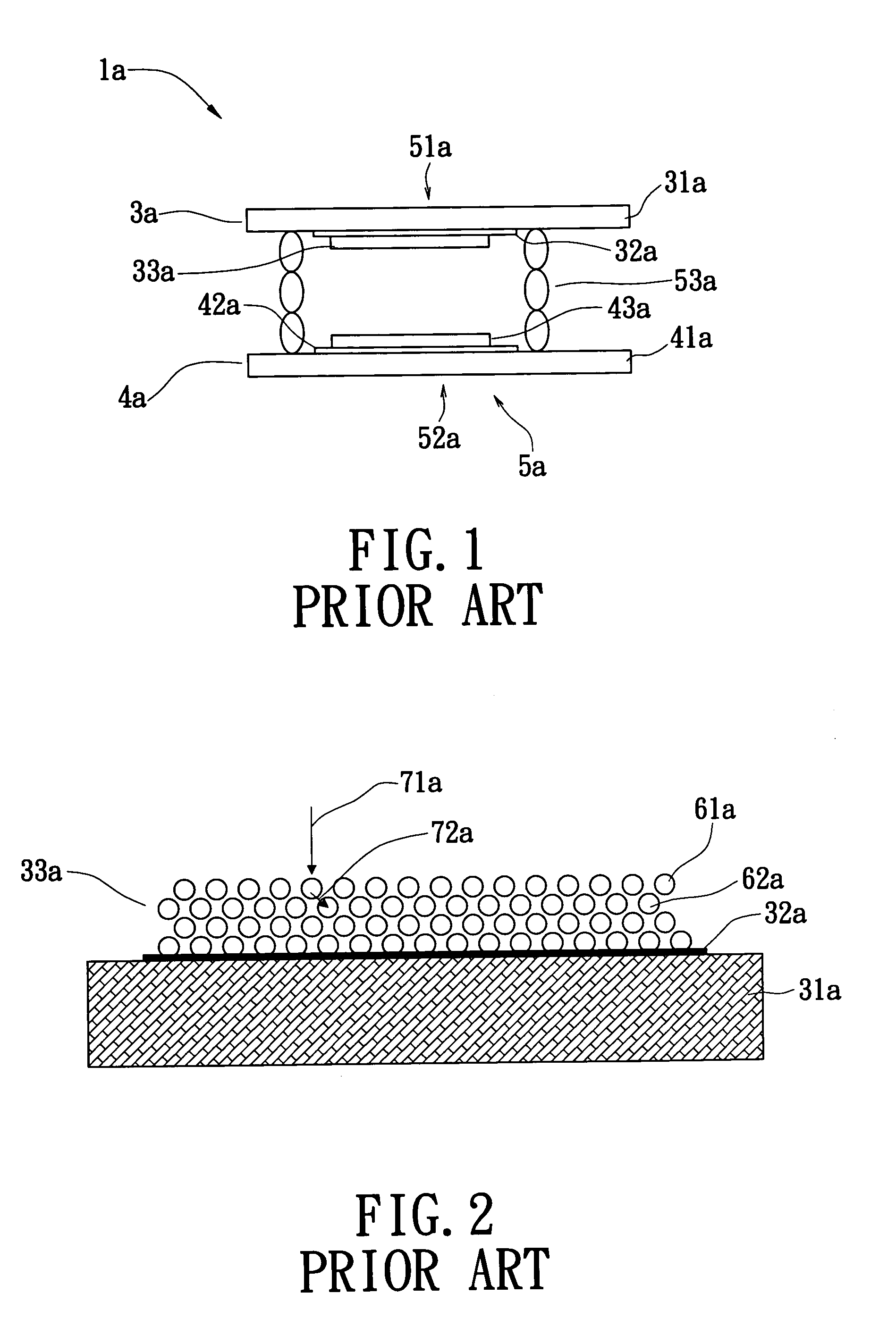
BACKGROUND OF THE INVENTION [0001] 1. Field of the Invention [0002] The present invention relates to a technique of coating a phosphor layer on a positive plate of a FED (Field Emission Display), and particularly relates to a technique of coating a phosphor layer on a positive plate of a FED by spaying. [0003] 2. Background of the Invention [0004] A FED is a device that utilizes a cathode electron emitter to generate surrounding electrons within an electric field; the electrons excite the phosphors coated on an anode for lighting. The FED is lightweight and thin, and the effect area thereof is variable to meet requirements, but without the view angle problems of flat LCD (Liquid Crystal Display). [0005]FIG. 1 shows a diode FED 1a including a unit 5a with an anode 3a and a cathode 4a disposed therein. The unit 5a includes a rib 53a arranged between the anode 3a and the cathode 4a for separating the anode 3a from the cathode 4a and for supporting therebetween. The anode 3a includes an...

Claims


Application Information

Patent Timeline
Patent Type & Authority Applications(United States)
IPC IPC(8): B05D5/06B05D5/12C09K11/02H01J31/12
CPCH01J31/127C09K11/02C09K11/642
Inventor LI, YU-ANHSIAO, SHIH CHIENLEE, SHIE HENGCHENG, KUEI WEN
Owner TECO NANOTECH CO LTD
Learn More