Semiconductor device, wiring substrate forming method, and substrate processing apparatus
a semiconductor device and substrate technology, applied in semiconductor devices, semiconductor/solid-state device details, electrical devices, etc., can solve the problems of high manufacturing cost, difficult scaling down, circuit damage, etc., and achieve easy and inexpensive high-speed planarization, easy fine control of thickness, and efficient removal of substrates
- Summary
- Abstract
- Description
- Claims
- Application Information
AI Technical Summary
Benefits of technology
Problems solved by technology
Method used
Image
Examples
first embodiment
[0053] (First Embodiment)
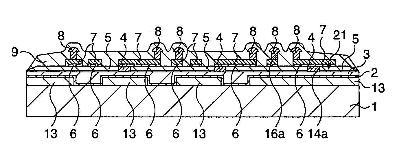
[0054] Here, a silicon semiconductor substrate (silicon wafer) is shown as an example of a substrate, and a case where a multilayer wiring formed by staking wirings in plural layers in an insulator is formed on the semiconductor substrate is disclosed.
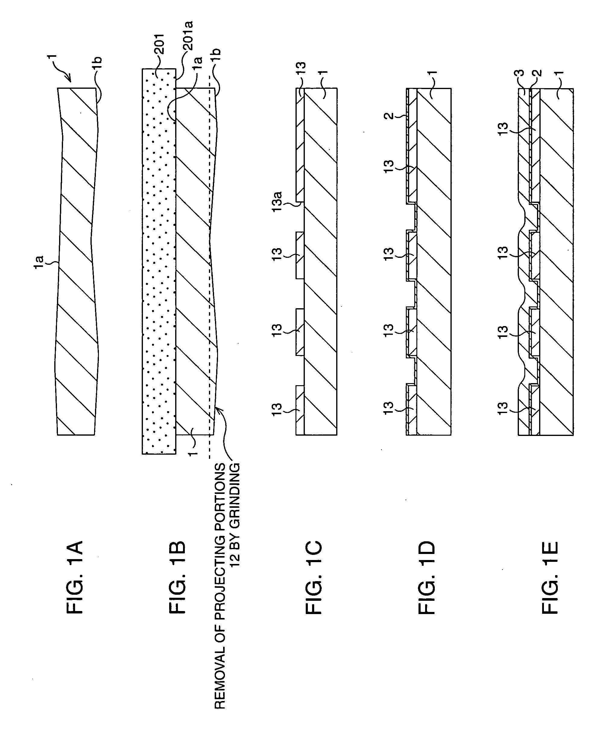
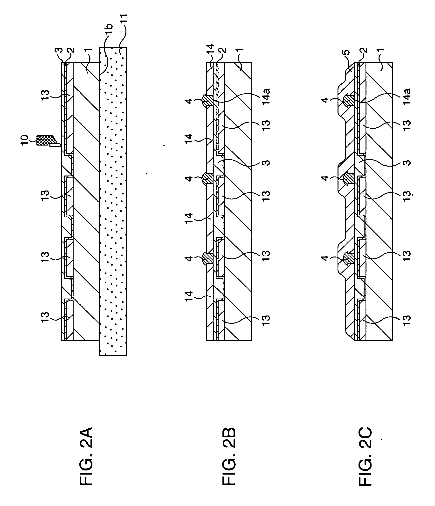
[0055]FIG. 1A to FIG. 1E, FIG. 2A to FIG. 2C, FIG. 3A to FIG. 3C, and FIG. 4A to FIG. 4C are schematic sectional views showing a multilayer wiring substrate forming method according to this embodiment step by step.
[0056] First, as shown in FIG. 1A, a silicon semiconductor substrate 1 is prepared. Usually, the silicon semiconductor substrate is not uniform in thickness as shown and besides has undulations.
[0057] Hence, as a preceding process to subject one principal surface of the semiconductor substrate 1, here a substrate front surface (wiring forming surface 1a), to cutting with a tool which will be described later, the other principal surface of the semiconductor substrate 1, here a back surface 1b (of th...
second embodiment
[0112] (Second Embodiment)
[0113] Here, a silicon semiconductor substrate is shown as an example of a substrate, and a case where a multilayer wiring layer formed by stacking a plurality of wiring layers each composed of wirings in an insulator is formed when an LSI is manufactured is disclosed.
[0114] Among semiconductor devices including a multilayer wiring layer are those which have forms such as shown in FIG. 13 and FIG. 14. In the semiconductor device in FIG. 13, electrodes 63a are formed so as to surround a periphery of an element region 302 where plural (many) semiconductor elements (MOS transistors or the like) are formed in a silicon semiconductor substrate 301, and the respective semiconductor elements and the electrodes 63a are electrically connected. On the other hand, in the semiconductor device in FIG. 14, plural electrodes 63a are formed in matrix in the semiconductor substrate 301, and plural (many) semiconductor elements are formed between the electrodes 63a. Namely,...
modification example
[0142] (Modification Example)
[0143] A modification example of this embodiment will be described below.
[0144] In this modification example, trace processing of a cutting surface is added in the cutting process with the tool explained in the second embodiment. An outline of this trace processing is shown in FIG. 21.
[0145] In the cutting with the tool according to the second embodiment, cutting in a wide range can be performed at low cost, in a short time, and with an extremely high degree of precision (nano-order flat roughness).
[0146] However, in this case, chippings are produced in cutting and sometimes adhere to the cutting surface. Out of insulating layers and wirings (including via portions) to be cut, chippings from an insulating material only adhere to the cutting surface by static electricity and therefore can be easily removed after cutting, but chippings from a wiring material, especially Au, are bonded to the cutting surface once they adhere thereto, and cannot be easily...
PUM
 Abstract
Description
Claims
Application Information
 - R&D
- Intellectual Property
- Life Sciences
- Materials
- Tech Scout
- Unparalleled Data Quality
- Higher Quality Content
- 60% Fewer Hallucinations
Browse by: Latest US Patents, China's latest patents, Technical Efficacy Thesaurus, Application Domain, Technology Topic, Popular Technical Reports.
© 2025 PatSnap. All rights reserved.Legal|Privacy policy|Modern Slavery Act Transparency Statement|Sitemap|About US| Contact US: help@patsnap.com


