Plasma processing apparatus and plasma processing method

a processing apparatus and plasma technology, applied in the field of plasma processing apparatus and plasma processing method, can solve the problems of unstable temperature at inconsistency, and radical concentration at the periphery of the outer ring body, and achieve the effects of increasing the thermal conductivity between the conductive ring body and the electrode, stable processing, and high consistency

Inactive Publication Date: 2005-08-11
TOKYO ELECTRON AT +1
View PDF12 Cites 60 Cited by
  • Summary
  • Abstract
  • Description
  • Claims
  • Application Information

AI Technical Summary

Benefits of technology

[0023] In this method, the temperature of the conductive ring body can be controlled by supplying the heat transfer gas at a specific supply pressure to the space between the conductive ring body and the electrode so as to set the temperature of the workpiece and the temperature of the conductive ring body roughly equal to each other. As a result, the thermal conductivity between the conductive ring body and the electrode can be increased. In addition, by regulating the level of the supply pressure of the heat transfer gas, the temperature of the conductive ring body can be adjusted as appropriate. During this process, it is desirable that the supply pressure of the neat transfer gas be controlled based upon temperature information obtained by measuring the temperature of the conductive ring body and the temperature of the workpiece. By adopting such a method, the temperature of the conductive ring body can be matched with the temperature of the workpiece which changes continuously during the processing. Furthermore, a high degree of consistency in the concentration of radicals distributed around the workpiece and the conductive ring body is achieved. Consequently, no discrepancy in the processing occurs between the center of the workpiece and the outer edges of the workpiece, to realize uniform processing over the entire surface of the workpiece.
[0024] It is desirable to implement an additional step in which heat is applied to an insulating ring body encompassing the periphery of the conductive ring body to maintain the temperature of the insulating ring body at a constant level during plasma processing performed on the workpiece. This maintains the temperature of the insulating ring body at a specific level before the start of processing. As a result, stable processing can be performed on the workpiece even immediately after the processing starts.

Problems solved by technology

As a result, when performing continuous processing, the temperature at the outer ring body in particular, is not stable, after the start of processing until a specific number of wafers have been processed.
If the temperature at the outer ring body is unstable, the radical concentration at the periphery of the outer ring body, e.g., at the area encompassing the outer edges of the wafer, becomes inconsistent.
Consequently, uniform processing is not achieved at the center of the wafer and at the outer edges of the wafer, resulting in difficulty in performing uniform processing over the entire wafer surface.

Method used


Image

  • Plasma processing apparatus and plasma processing method
  • Plasma processing apparatus and plasma processing method
  • Plasma processing apparatus and plasma processing method

Examples


first embodiment

(1) Overall Structure of the Etching Apparatus

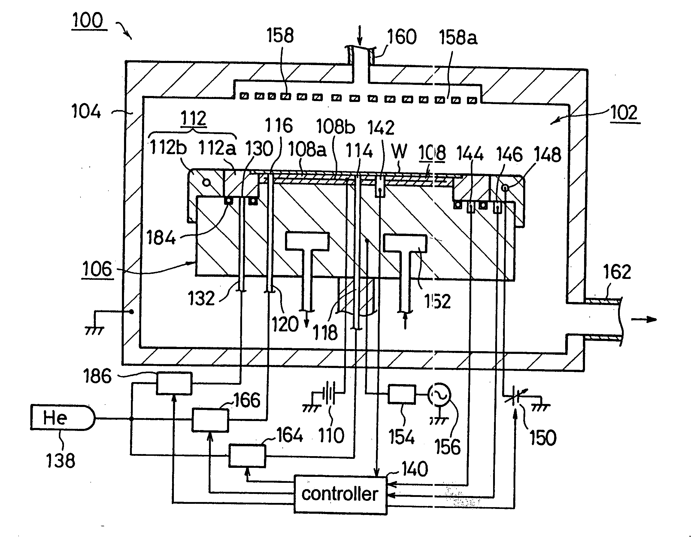
[0037] First, in reference to FIGS. 1 and 2, the overall structure of an etching apparatus 100 that may adopt the present invention is explained.

[0038] A processing chamber 102 of the etching apparatus 100 in FIG. 1 is formed inside a grounded, airtight processing container 104. A lower electrode 106 is provided inside the processing chamber 102. The lower electrode 106 also functions as a mounting stage on which a wafer W is placed. In addition, the lower electrode 106, which is constituted of a conductive metal achieving a high thermal conductivity such as aluminum, is formed in a roughly cylindrical shape. An electrostatic chuck 108 is provided at the mounting surface of the lower electrode 106. The electrostatic chuck 108 is constituted by clamping an electrode 108b with a thin film 108a which may be formed from, for instance, polyimide. The wafer W mounted on the electrostatic chuck 108 structured as described above is held onto ...

second embodiment

[0060] Next, in reference to FIG. 5, an etching apparatus 200 in the second embodiment, which may adopt the present invention, is explained.

[0061] A lower electrode 202 of the etching apparatus 200 is internally provided with a third gas supply pipe 204. The third gas supply pipe 204 is connected to the third gas supply duct 130 and the second gas supply pipe 120. When this structure is adopted, the pressure of He supplied by the gas supply source 138 is first adjusted by the second pressure regulating unit 166 to a specific level, e.g., approximately 40 Torr. Then, the He is supplied to the space between the outer edges of the wafer W and the electrostatic chuck 108 via the second gas supply pipe 120 and the second gas supply duct 116. The, He is also supplied to the space between the inner ring body 112a and the lower electrode 202 via the second gas supply pipe 120, the third gas supply pipe 204 and the third gas supply duct 130. It is to be noted that other structural features ...

third embodiment

[0063] An etching apparatus 500 in the third embodiment that may adopt the present invention is now explained in reference to FIG. 6.

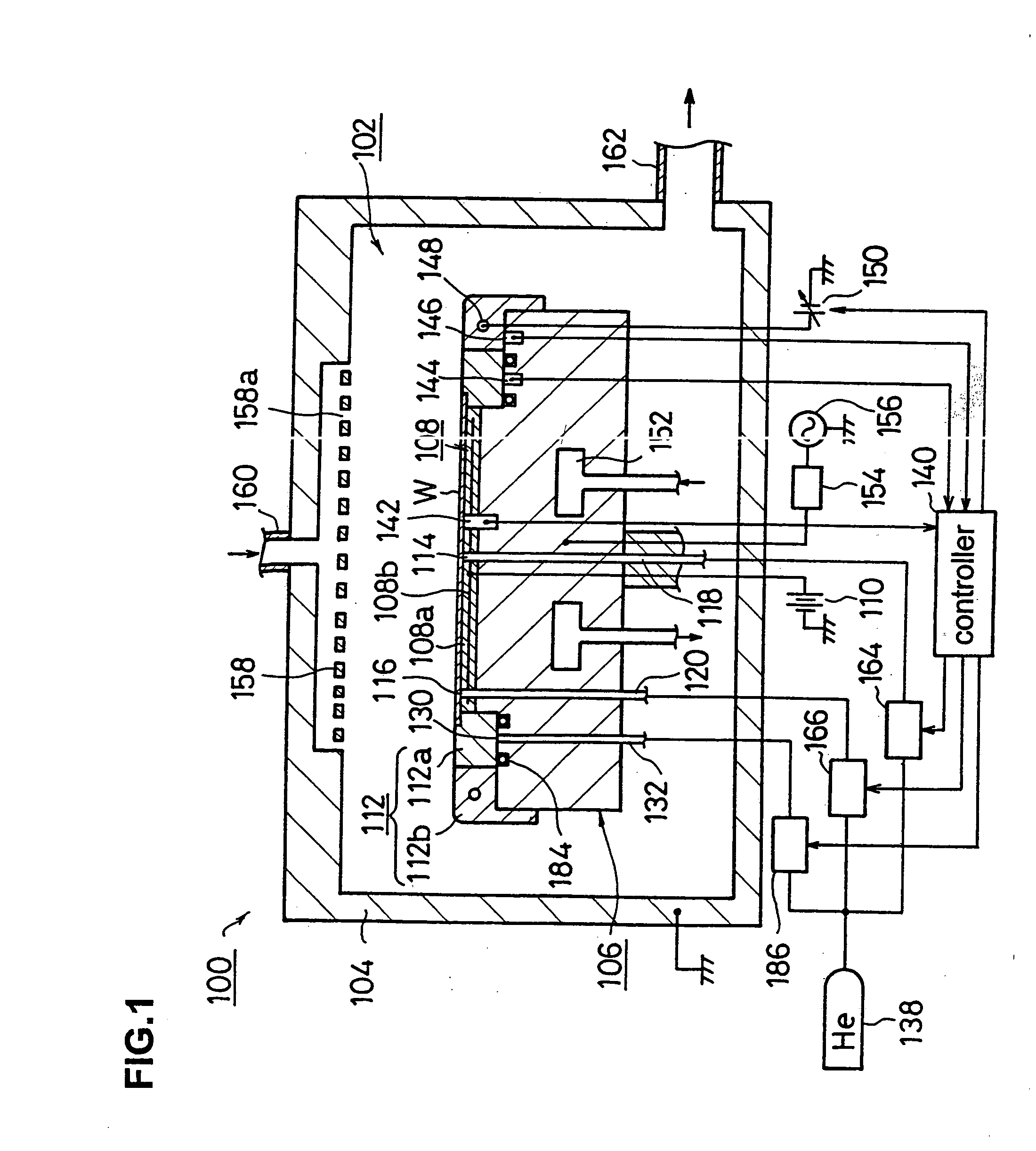
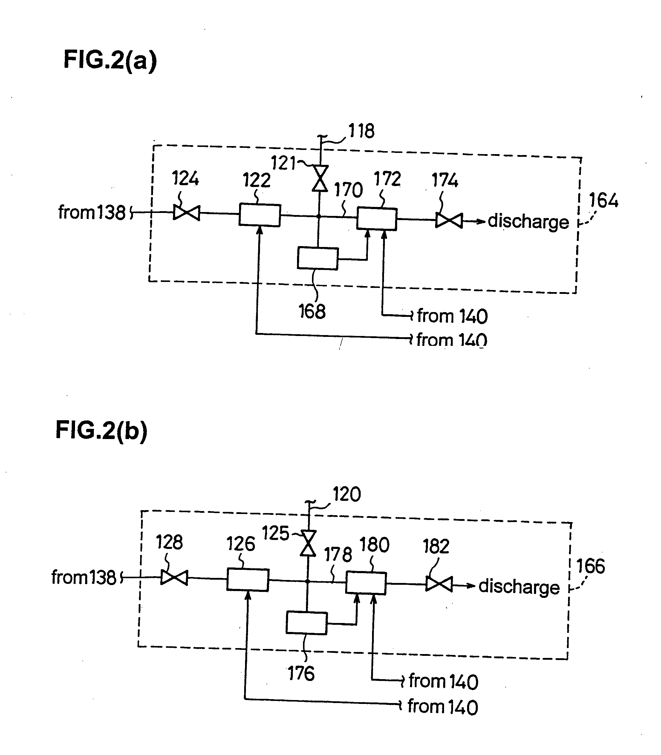
[0064] He achieving a first pressure level, e.g., 7 Torr, is supplied via the first pressure regulating unit 164 to the first gas supply pipe 118 of the etching apparatus 500. He achieving a second pressure level, e.g., 40 Torr, is supplied via the second pressure regulating unit 166 to the second gas supply pipe 120. A third gas supply pipe 502 is connected to a third gas supply duct 130. The third gas supply pipe 502 is connected to the first gas supply pipe 118 and to the second gas supply pipe 120 respectively via a first link pipe 521 and a second link pipe 522. The first link pipe 521 is provided with a first open / close valve 511 and the second link pipe 522 is provided with a second open / close valve 512. The first open / close valve 511 and the second open / close valve 512 are both connected to the controller 140.

[0065] By adopting this structure...


PUM

PropertyMeasurementUnit
voltageaaaaaaaaaa
temperatureaaaaaaaaaa
frequencyaaaaaaaaaa

Abstract

An electrostatic chuck 108 is provided on a lower electrode 106 provided inside a processing chamber 102 of an etching apparatus 100, and a conductive inner ring body 112a and an insulating outer ring body 112b are encompassing the outer edges of a wafer W mounted on the chuck surface. The temperatures of the wafer W and the inner and outer ring bodies 112a and 112b are detected by first third temperature sensors 142, 144 and 146. A controller 140 controls the pressure levels of He supplied to the space between the center of the wafer W and the electrostatic chuck 108 via first gas outlet ducts 114 and to the space between the outer edges of the wafer W and the electrostatic chuck 108 via second gas outlet ducts 116 and the quantity of heat generated by a heater 148 inside the outer ring body 112b based upon the information on the temperatures thus detected so that the temperatures of the wafer W and the inner ring body 112a are set roughly equal to each other.

Description

TECHNICAL FIELD [0001] The present invention relates to a plasma processing apparatus and a plasma processing method. BACKGROUND ART [0002] A plasma,etching apparatus is utilized during the process of manufacturing a semiconductor device in the prior art. In the processing chamber of the apparatus, an upper electrode and a lower electrode are set facing opposite each other. In the plasma etching apparatus adopting this structure, the processing gas introduced into the processing chamber is raised to plasma when high-frequency power is applied to the lower electrode and the workpiece placed on the lower electrode, such as a semiconductor wafer (hereafter referred to as a “wafer”) becomes etched. In addition, the lower electrode is internally provided with a temperature control mechanism to adjust the wafer temperature. The lower electrode is also provided with a ring body. The ring body is constituted of an inner ring body and an outer ring body. The inner ring body is set so as to e...

Claims


Application Information

Patent Timeline
Patent Type & Authority Applications(United States)
IPC IPC(8): C23C16/00C23F4/00H05H1/46H01L21/205H01L21/302H01L21/3065H01L21/68H01L21/683H05H1/00
CPCH01J37/32623H01J37/32642Y10S156/915H01L21/67248H01L21/6831H01J2237/2001H01L21/3065
Inventor KOSHIMIZU, CHISHIOISHIHARA, HIROYUKIHIGUCHI, KIMIHIROMARUYAMA, KOJI
Owner TOKYO ELECTRON AT
Why Eureka
Try Eureka