
Methods of making a multi-well test plate having an adhesively secured transparent bottom panel

a multi-well, transparent technology, applied in laboratory glassware, laboratory apparatus, chemistry apparatus and processes, etc., can solve the problems of adhesive migration into the test well, difficulty in achieving a seal in the surrounding relationship to each individual, and insufficient adhesion around the bottom of each well,

Inactive Publication Date: 2005-08-11
NALGE NUNC INTERNATIONAL
View PDF56 Cites 18 Cited by
  • Summary
  • Abstract
  • Description
  • Claims
  • Application Information

AI Technical Summary

Benefits of technology

"The invention provides a method for making a multi-well test plate by applying adhesive to the transparent panel or the upper frame portion and then curing it to bond the two together. The adhesive is applied in a pattern that does not contaminate or touch the work areas on the optical surface of the transparent panel. This method allows for the creation of a reliable and efficient multi-well test plate."

Problems solved by technology

When applying a panel to the bottom of the framework, for example, it has been difficult to achieve a seal in surrounding relationship to each individual test well.
Conventional manufacturing methods involving an adhesive securement of the transparent panel to the test well framework may result in inadequate adhesion, inadequate sealing around the bottom of each well, adhesive migration into the test wells or other problems.
Adhesive migration into the test wells is particularly troublesome as the presence of the adhesive in on the work area of the optical surface may potentially alter the assay results.
Moreover, the presence of adhesive in these work areas may interfere with the creation and reading of microassays, cell adhesion and growth, and binding and assaying of nucleic acids, proteins, etc. among other artifacts.

Method used


Image

  • Methods of making a multi-well test plate having an adhesively secured transparent bottom panel
  • Methods of making a multi-well test plate having an adhesively secured transparent bottom panel
  • Methods of making a multi-well test plate having an adhesively secured transparent bottom panel

Examples


Embodiment Construction

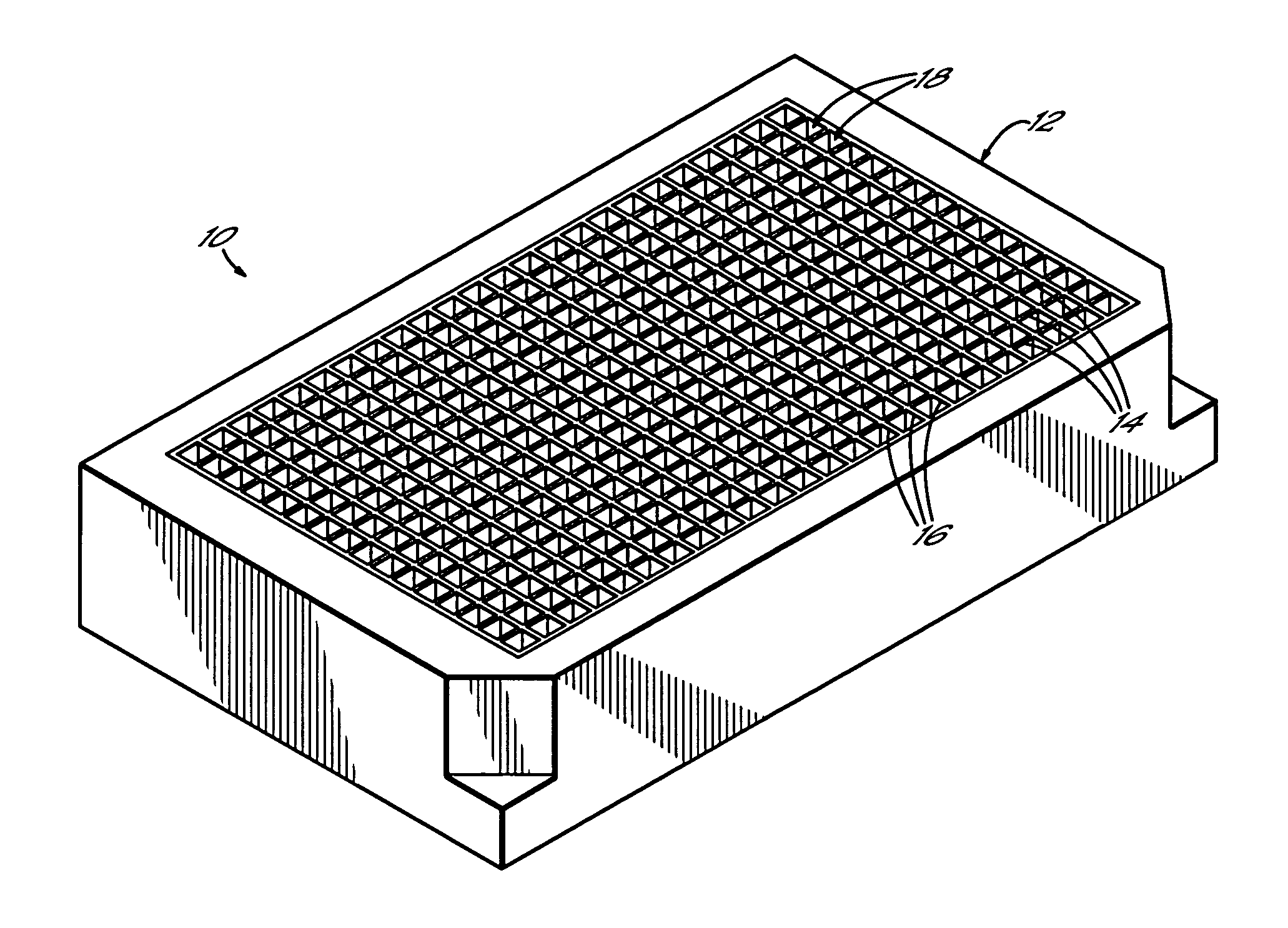
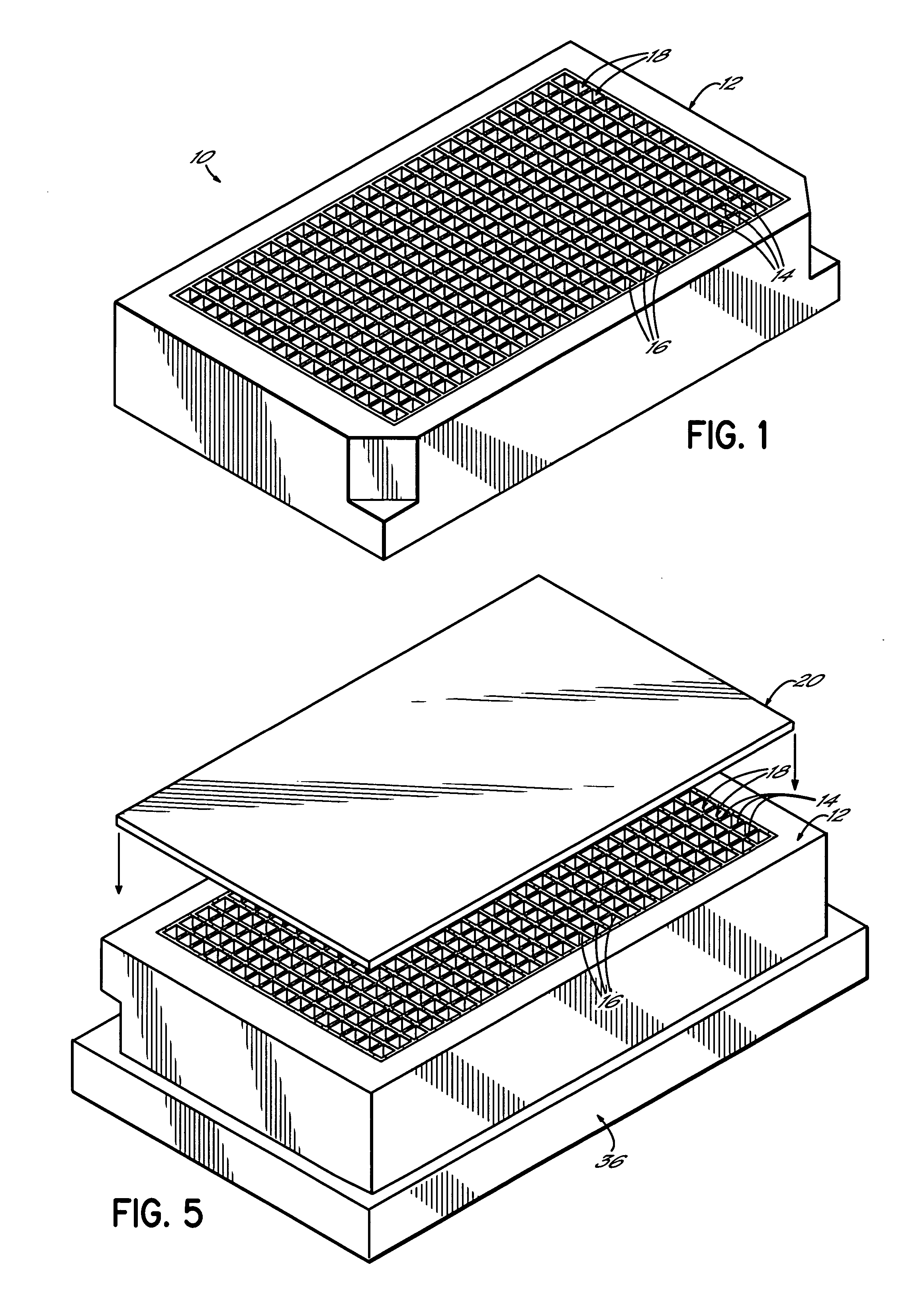
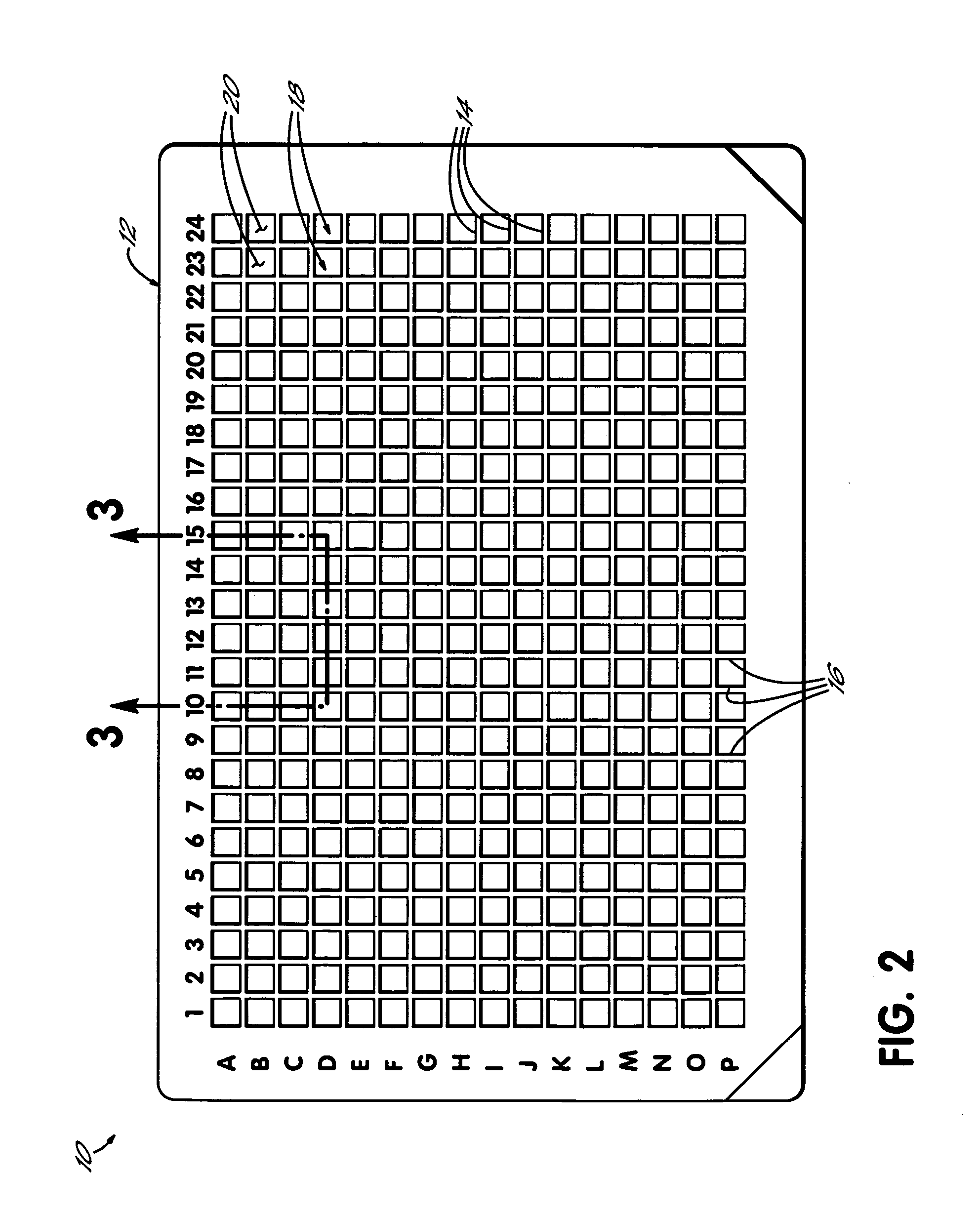
[0022] Referring first to FIGS. 1-3, a multi-well test plate 10 constructed in accordance with one preferred embodiment of the invention generally comprises an upper frame portion 12 having a plurality of walls 14, 16. Upper frame portion 12 is preferably formed from a polymer, such as polystyrene, and is preferably opaque. Other polymer resins suitable for forming upper frame portion 12 include, but are not limited to, polyolefins (e.g., polypropylene, high density polyethylene, and polymethylpentene), cyclic olefin polymers and copolymers, acrylics, polyesters, polycarbonate, polystyrene, high impact polystyrene, and polysulfone. Depending on the intended use of test plate 10, upper frame portion 12 can be transparent, translucent, or opaque. In specific embodiments, the upper frame portion 12 may be white, which provides advantageous light reflective properties, or black, which has advantageous light absorptive properties. Walls 14, 16 define independent wells 18 for receiving li...


PUM

PropertyMeasurementUnit
viscosityaaaaaaaaaa
transparentaaaaaaaaaa
flexibleaaaaaaaaaa

Abstract

Methods of making a multi-well test plate including an upper frame portion and a transparent panel secured to a lower side of the upper frame portion with adhesive. The upper frame portion includes a plurality of walls defining adjacent wells for receiving assay samples. The adhesive may be applied to either the transparent panel or the upper frame portion by various techniques including, but not limited to, transfer printing, robotic dispensing, silk screening, flexographic printing, and pad printing.

Description

FIELD OF THE INVENTION [0001] The invention generally relates to multi-well test plates for assaying liquid samples and, more particularly, to methods of making a multi-well test plate having a panel adhesively bonded to a framework defining test wells for containing the liquid samples. BACKGROUND OF THE INVENTION [0002] Multi-well test plates or micro-plates are well known in scientific areas such as biotechnology, for use in the detection and measurement of substances present in translucent liquid samples. Generally, the light absorbence characteristics of the sample are measured through one or more spectroscopy procedures. Typically, a framework of test wells in the test plate is open at the top for receiving the liquid samples and is closed with a transparent bottom that allows light radiation penetration in a wavelength region necessary for a particular study. These studies, commonly referred to assays, may include drug concentration assays, drug metabolite assays, enzyme activ...

Claims


Application Information

Patent Timeline
Patent Type & Authority Applications(United States)
IPC IPC(8): B01L3/00B29C65/52
CPCB01L3/5085B29C65/4845B01L2200/12B01L2300/0851B29C65/526B29C66/863B01L2200/0689B29C65/4835B29C65/483B29C66/542B29C65/524B29C65/00B29C66/534B29C65/52B29C66/112B29C66/114B29C66/53461B29C66/71B29C66/73365B29C66/8322B29K2081/06B29K2069/00B29K2067/00B29K2033/12B29K2033/08B29K2025/08B29K2025/06B29K2023/38B29K2023/18B29K2023/12B29K2023/065B29K2023/00
Inventor RINGLEBEN, RONALD D.HARRIS, SCOTT A.
Owner NALGE NUNC INTERNATIONAL
Learn More