Color filter and electro-optical device

a color filter and electrooptical technology, applied in the direction of instruments, luminescnet screens, discharge tubes, etc., can solve the problems of reducing the volume of ink, and affecting the quality of ink

Inactive Publication Date: 2005-08-11
KATEEVA
View PDF8 Cites 16 Cited by
  • Summary
  • Abstract
  • Description
  • Claims
  • Application Information

AI Technical Summary

Benefits of technology

[0009] Hence an object of this invention is to provide a color filter and display device in which differences in the quality (volume, surface height, surface flatness, or similar) of liquid material after drying and hardening are suppressed, so that there are no color irregularities, color tone irregularities, or light intensity irregularities.
[0010] A further object of this invention is to provide a color filter and display device in which the color filter surface is made smooth, enabling the uniform distribution of a liquid crystal layer formed on the color filter.
[0011] In order to resolve the above-mentioned problems, a color filter of this invention comprises pixels which are separated from each other by partitions formed on a substrate so as to comprise a plurality of color elements of ink. The light transmittance characteristics in each pixel are substantially uniform among pixels.

Problems solved by technology

However, in such a color filter, if there is insufficient control of the ink surface level of the discharged ink, the volume of the ink after drying and hardening may be too large, with ink accumulated upwards beyond the height of the partitions on the substrate; or, the volume after drying and hardening may be too small, resulting in a depressed shape.
For example, after ink discharge, if drying is performed under high-temperature conditions, the drying advances too rapidly, and there is a tendency for the ink volume to be reduced.
Conversely, if dried under low-temperature conditions, the drying is too slow, and the ink volume after drying tends not to be reduced very much.
Such a difference in ink surface levels on the same substrate causes color irregularities and color tone differences, and is undesirable.
Such problems also occur in other electro-optical devices besides color filters.
Further, because the surfaces of coloring layers and banks are not always flat, when a protective layer is for example formed on the coloring layer and banks in fabricating a color filter, which is used in a liquid crystal display device, the surface of the protective layer may not be flat, and the distribution of the liquid crystal layer may not be flat.

Method used


Image

  • Color filter and electro-optical device
  • Color filter and electro-optical device
  • Color filter and electro-optical device

Examples


first embodiment

[0035] 1-1. First embodiment

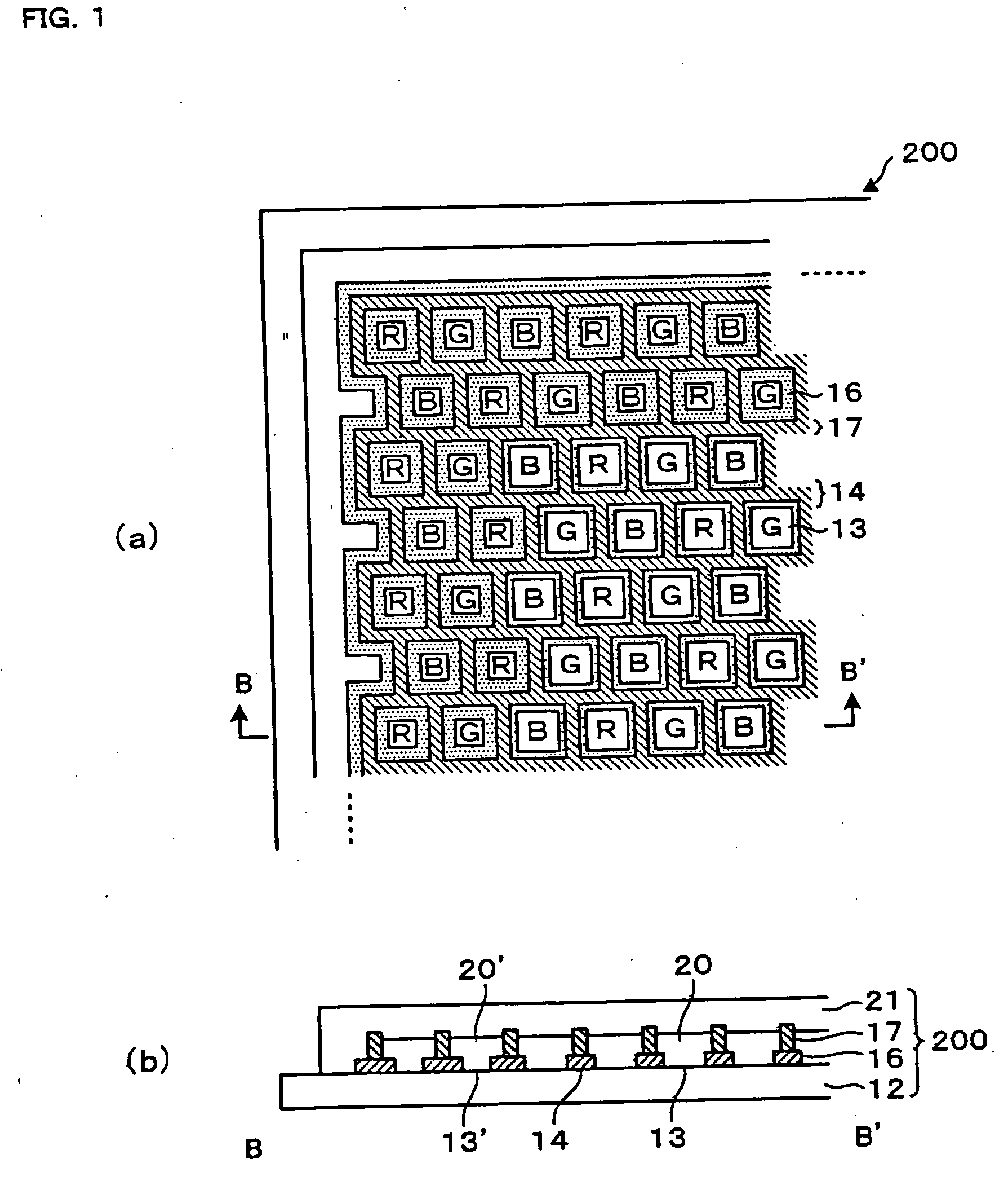
[0036]FIG. 1 is a partial enlarged view of a color filter of a first embodiment of this invention. FIG. 1(a) is a plan view, and FIG. 1(b) is a cross-sectional view along line B-B′ in FIG. 1(a).

[0037] As shown in FIG. 1(a), the color filter 200 comprises pixels 13 arranged in a matrix on the transparent substrate 12; the boundaries between the pixels are divided by partitions 14. Into each of the pixels 13 is introduced an ink in one of the colors red (R), green (G), and blue (B). In this example, the colors red, green, and blue are arranged in a so-called mosaic array. However, other arrangements, such as a stripe array or a delta array, may be used.

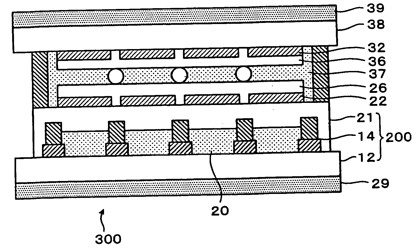
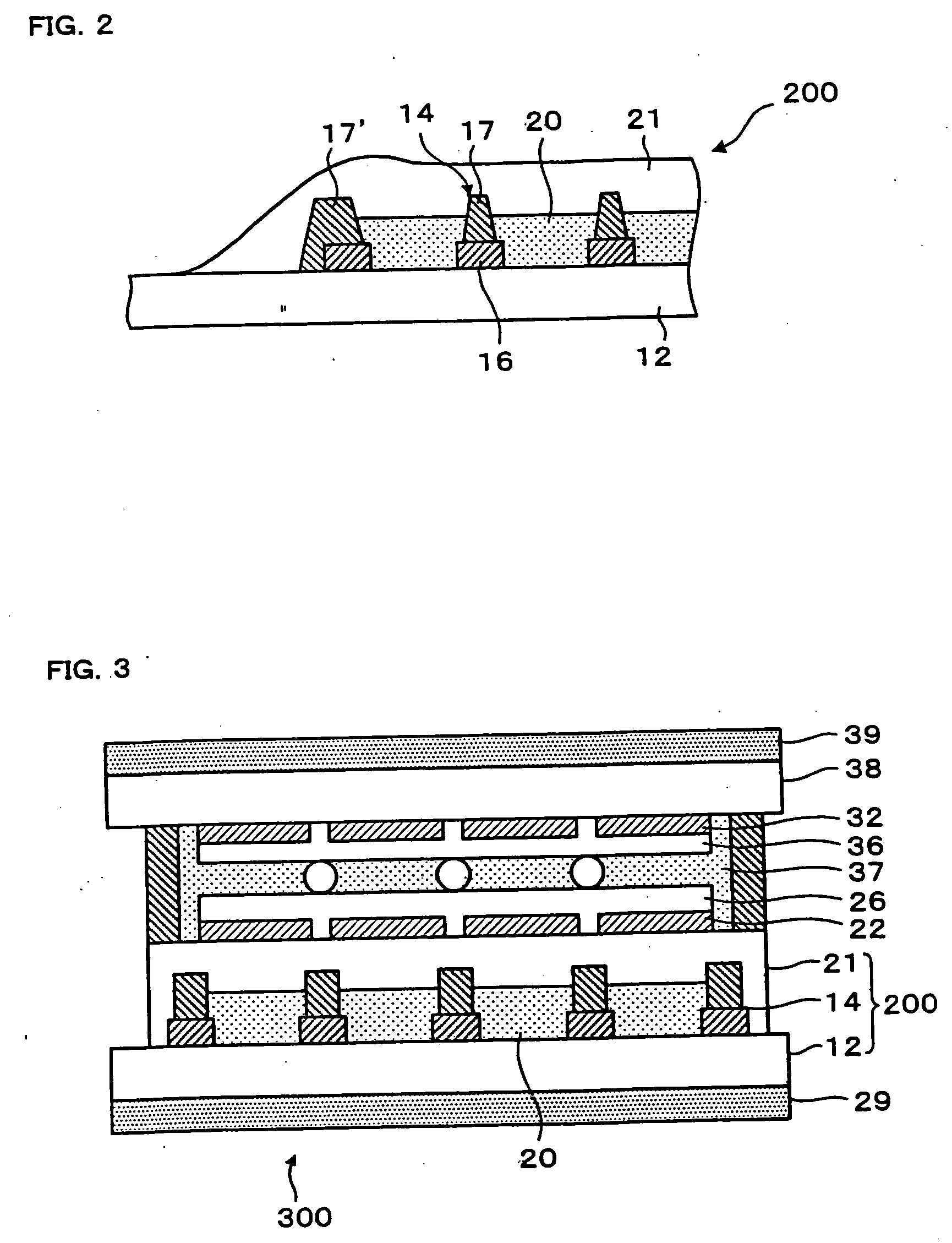
[0038] As shown in FIG. 1(b), the color filter 200 comprises a transparent substrate 12 and light-shielding partitions 14. The pixels 13 are formed in portions in which the partitions 14 are not formed (are removed). The inks of different colors introduced into the pixels 13 constitute the coloring layer 20...


PUM

PropertyMeasurementUnit
thicknessaaaaaaaaaa
thicknessaaaaaaaaaa
thicknessaaaaaaaaaa

Abstract

A color filter (200) comprises pixels (13) separated from each other by partitions (14) formed on a substrate (12) so as to have a plurality of color elements of ink. Dummy pixels (13′) are formed outside the area in which the pixels (13) are formed. The amount of ink applied to each of said pixels and the amount of ink applied to each of said dummy pixels are substantially equal. A protective film (21) covering said pixels (13) is formed so as to also cover said dummy pixels (13′).

Description

TECHNICAL FIELD [0001] This invention relates to a color filter and electro-optical device, and in particular to a color filter and electro-optical device with improved uniformity between pixels in optical transmittance characteristics in each individual pixel. BACKGROUND ART [0002] A color filter is known to be used in color liquid crystal display devices or other display devices. Such color filter is manufactured by forming matrix-shaped partitions, functioning as shielding portions and banks, on a transparent substrate, and then using an ink jet method to apply coloring materials within the partitions, followed by baking at a prescribed temperature, drying, and hardening. [0003] In this conventional color filter manufacturing method, when liquid material is discharged, the liquid material is applied to the extent of accumulating above the height of the partitions on the substrate. When this is baked at a prescribed temperature, dried and hardened, the volume is reduced, and the h...

Claims


Application Information

Patent Timeline
Patent Type & Authority Applications(United States)
IPC IPC(8): G02B5/20G02F1/1335H01J11/12H01J11/24H01J11/26H01J11/44H01L27/32
CPCG02B5/201G02F1/133512H01L27/3246H01L27/3223H01L27/3244H01L27/3211H10K59/353H10K59/88H10K59/122H10K59/12G02F1/1335
Inventor KIGUCHI, HIROSHIARUGA, HISASHIKATAGAMI, SATORU
Owner KATEEVA
Why Eureka
Try Eureka