Liquid crystal display system with lamp feedback

Inactive Publication Date: 2005-08-11
O2 MICRO INT LTD
View PDF99 Cites 71 Cited by
  • Summary
  • Abstract
  • Description
  • Claims
  • Application Information

AI Technical Summary

Benefits of technology

[0007] Under an alternative embodiment, the liquid crystal display system comprises a liquid crystal display panel; a cold cathode fluorescent lamp for illuminating said liquid crystal display panel; a secondary transformer winding coupled to said cold cathode fluorescent lamp for providing current to said cold cathode fluorescent lamp; a primary transformer winding coupled to said secondary transformer winding for providing magnetic f

Problems solved by technology

When applied to a CCFL load, this circuit produces a “beat” effect in the CCFLs, which is both noticeable and undesirable.
Each of these references suffers from low efficiency, two-stage power conversion, variable-frequency operation, and/or load dependence.
Additionally, when t

Method used


Image

  • Liquid crystal display system with lamp feedback
  • Liquid crystal display system with lamp feedback
  • Liquid crystal display system with lamp feedback

Examples


Example

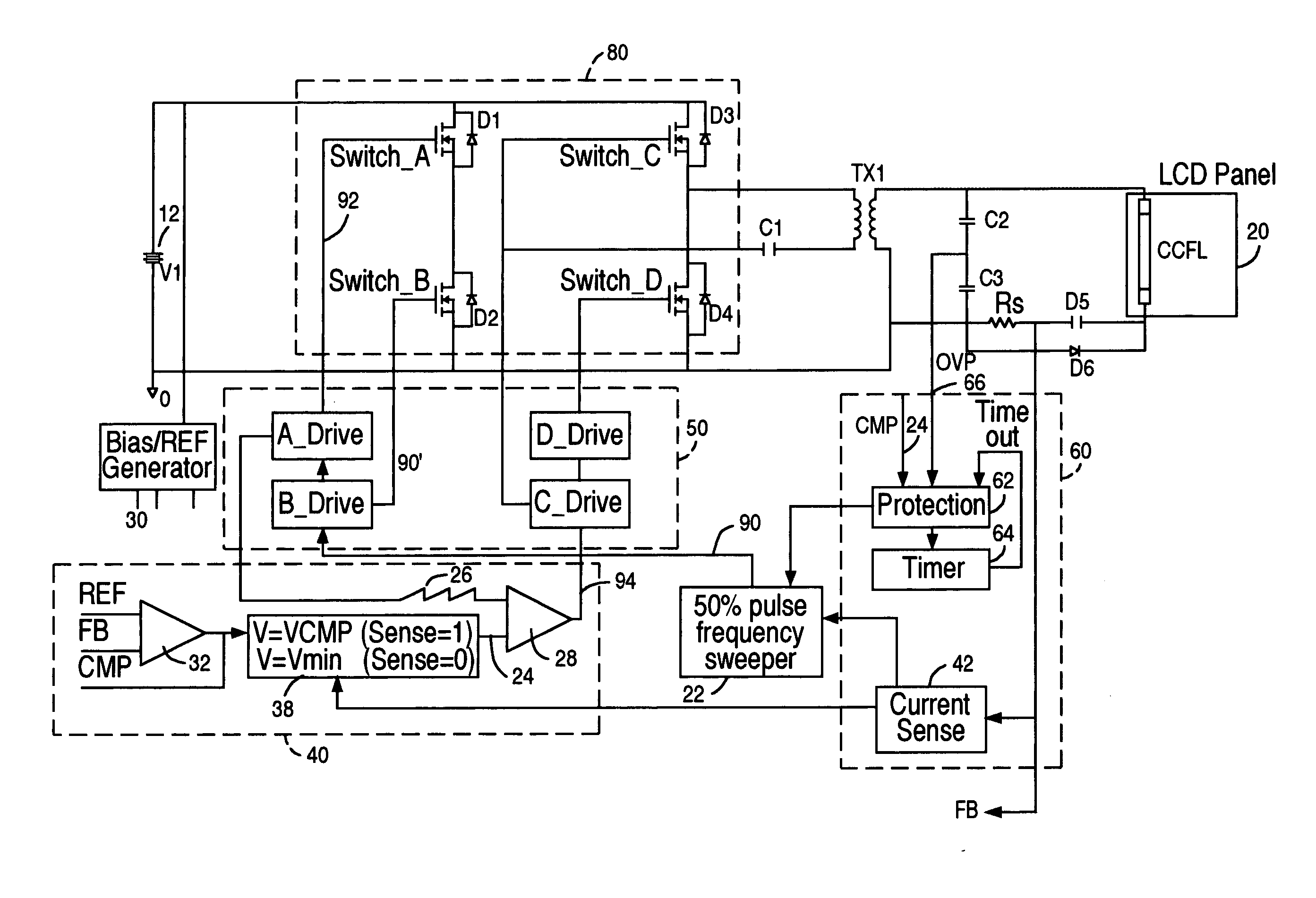
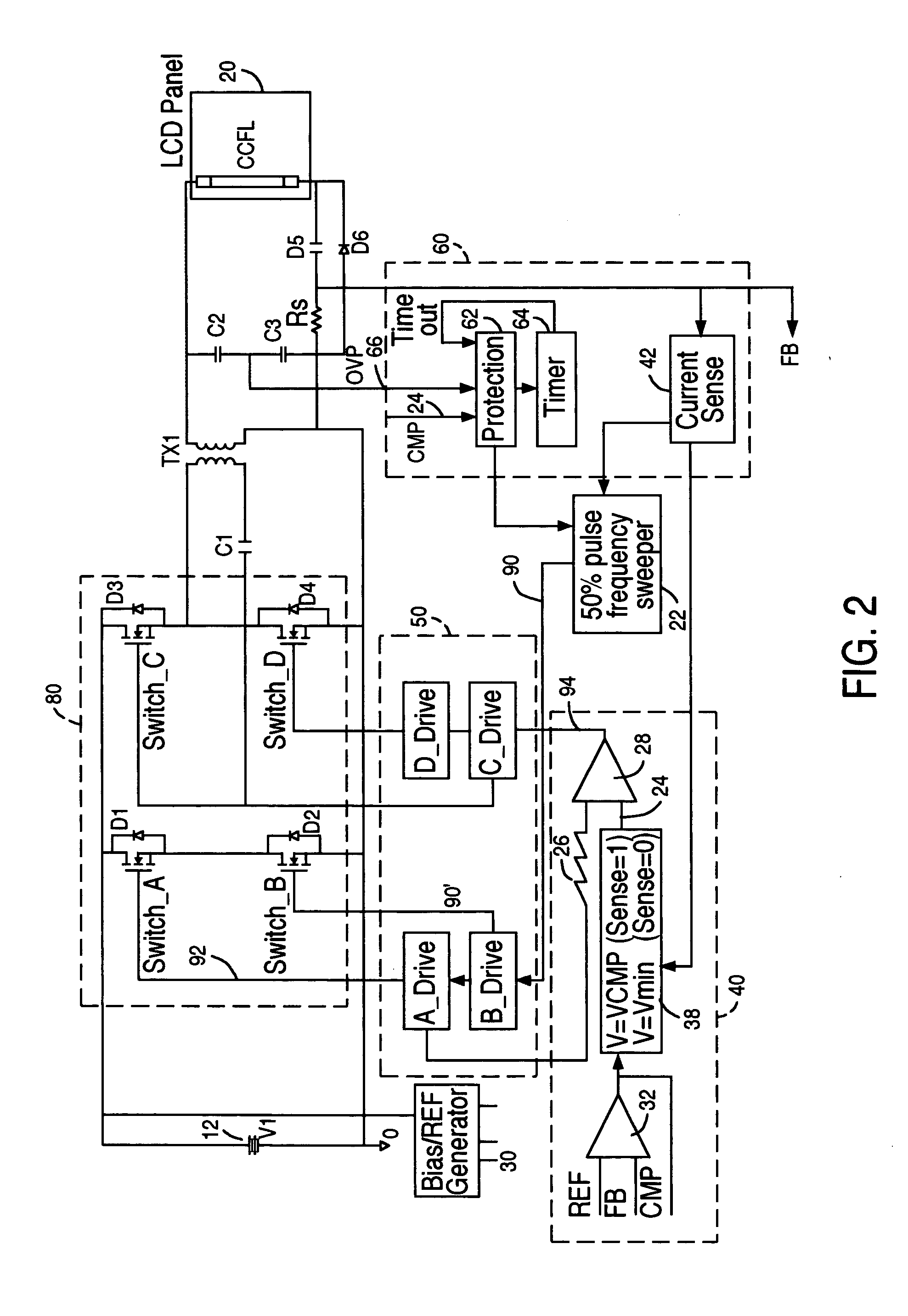
[0023] While not wishing to be bound by example, the following Detailed Description will proceed with reference to a CCFL panel as the load for the circuit of the present invention. However, it will be apparent that the present invention is not limited only to driving one or CCFLs, rather, the present invention should be broadly construed as a power converter circuit and methodology independent of the particular load for a particular application.

[0024] As an overview, the present invention provides circuitry to controllably deliver power to a load using feedback signals and pulse signals to adjust the ON time of two pairs of switches. When one pair of switches are controllably turned ON such that their ON times overlap, power is delivered to a load (via a transformer), along a conduction path defined by the pair of switches. Likewise, when the other pair of switches are controllably turned ON such that their ON times overlap, power is delivered to a load (via a transformer), along ...


PUM


Abstract

A liquid crystal display system and CCFL power converter circuit is provided using a high-efficiency zero-voltage-switching technique that eliminates switching losses associated with the power MOSFETs. An optimal sweeping-frequency technique is used in the CCFL ignition by accounting for the parasitic capacitance in the resonant tank circuit. Additionally, the circuit is self-learning and is adapted to determine the optimum operating frequency for the circuit with a given load. An over-voltage protection circuit can also be provided to ensure that the circuit components are protected in the case of open-lamp condition.

Description

FIELD OF THE INVENTION [0001] The present invention is directed to a DC to AC power converter circuit. More particularly, the present invention provides a high efficiency controller circuit that regulates power delivered to a load using a zero-voltage-switching technique. General utility for the present invention is found as a circuit for driving one or more Cold Cathode Fluorescent Lamps (CCFLs), however, those skilled in the art will recognize that the present invention can be utilized with any load where high efficiency and precise power control is required. DESCRIPTION OF RELATED ART [0002]FIG. 1 depicts a convention CCFL power supply system 10. The system broadly includes a power supply 12, a CCFL driving circuit 16, a controller 14, a feedback loop 18, and one or more lamps CCFL associated with an LCD panel 20. Power supply 12 supplies a DC voltage to circuit 16, and is controlled by controller 14, through transistor Q3. Circuit 16 is a self-resonating circuit, known as a Roye...

Claims


Application Information

Patent Timeline
IPC IPC(8): H02M3/24H02M3/337H05B41/282H05B41/285
CPCH02M3/3376H05B41/2828Y02B70/1433Y02B20/185H05B41/2855Y02B20/00Y02B70/10
Inventor LIN, YUNG-LINLIU, DA
Owner O2 MICRO INT LTD
Why Eureka
Try Eureka