Device for changing the shape of the mitral annulus

a technology of mitral valve and annulus, which is applied in the field of endovascular devices, can solve the problems of mitral and tricuspid leaflet tethering and incomplete coaptation in systole, and high morbidity and mortality in these patients, so as to reduce the circumference of the mitral valve annulus, reduce the trauma to the intima of the coronary sinus, and reduce the distance

Inactive Publication Date: 2005-08-11
EDWARDS LIFESCIENCES AG
View PDF99 Cites 335 Cited by
  • Summary
  • Abstract
  • Description
  • Claims
  • Application Information

AI Technical Summary

Benefits of technology

[0018] The invention described herein provides a more reliable and a safer way to treat a dilated mitral annulus. Devices in accordance with principles of the present invention may comprise one or more components suitable for deployment in the coronary sinus and adjoining coronary veins. The devices may be configured to bend in-situ to apply a compressive load to the mitral valve annulus with or without a length change, or may include multiple components that are drawn or contracted towards one another to remodel the mitral valve annulus. Any of a number of types of anchors may be used to engage the surrounding vein and tissue, including anchors comprising ultraviolet (UV) curable materials, hydrogels, hydrophilic materials, or biologically anchored components. Remodeling of the mitral valve annulus may be accomplished during initial deployment of the device, or by biological actuation during subsequent in-dwelling of the device.

Problems solved by technology

Heart valve regurgitation, or leakage from the outflow to the inflow side of a heart valve, is a common occurrence in patients with heart failure and a source of morbidity and mortality in these patients.
These geometric alterations result in mitral and tricuspid leaflet tethering and incomplete coaptation in systole.
Such a procedure is associated with high morbidity and mortality.
Due to the risks associated with this procedure, many of the sickest patients are denied the potential benefits of surgical correction of mitral regurgitation.
In addition, patients with moderate, symptomatic mitral regurgitation are denied early intervention and undergo surgical correction only after the development of cardiac dysfunction.
Unfortunately, however, the invasive nature of mitral valve surgery and the attendant risks render most heart failure patients poor surgical candidates.

Method used


Image

  • Device for changing the shape of the mitral annulus
  • Device for changing the shape of the mitral annulus
  • Device for changing the shape of the mitral annulus

Examples


first embodiment

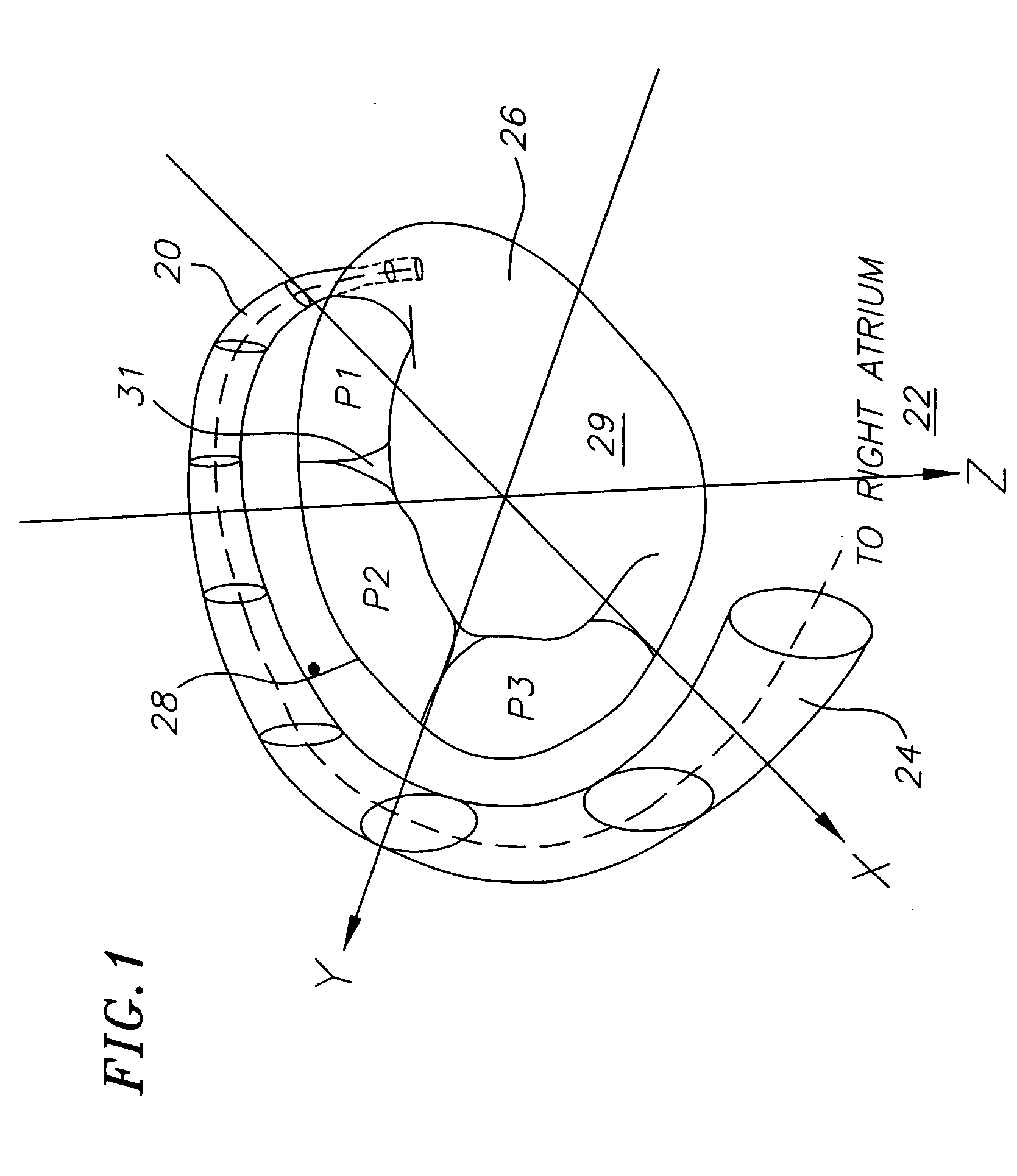
[0108] The device of the first embodiment is deployed as follows. As shown in FIG. 4, the elongate body 10, in the compressed state, is mounted onto a first balloon 58, which acts as a delivery catheter. The first balloon 58 has a length generally corresponding tn the length of the distal stent section 14 and is inserted so that it is enveloped by the distal stent section. The elongate body 10 and the first balloon 58 are inserted into the coronary sinus 20 from the coronary sinus ostium 24, e.g., until the central stent section 16 is generally aligned with the P2 scallop. Once the elongate body 10 and the first balloon 58 are positioned in the coronary sinus, the first balloon is expanded by introducing, for example, a saline solution through the delivery catheter and into the balloon. Alternately, any biocompatible solution may be used to inflate the balloon. The force of the expansion of the first balloon 58 expands the distal stent section 14 so that its circumference is forced ...

third embodiment

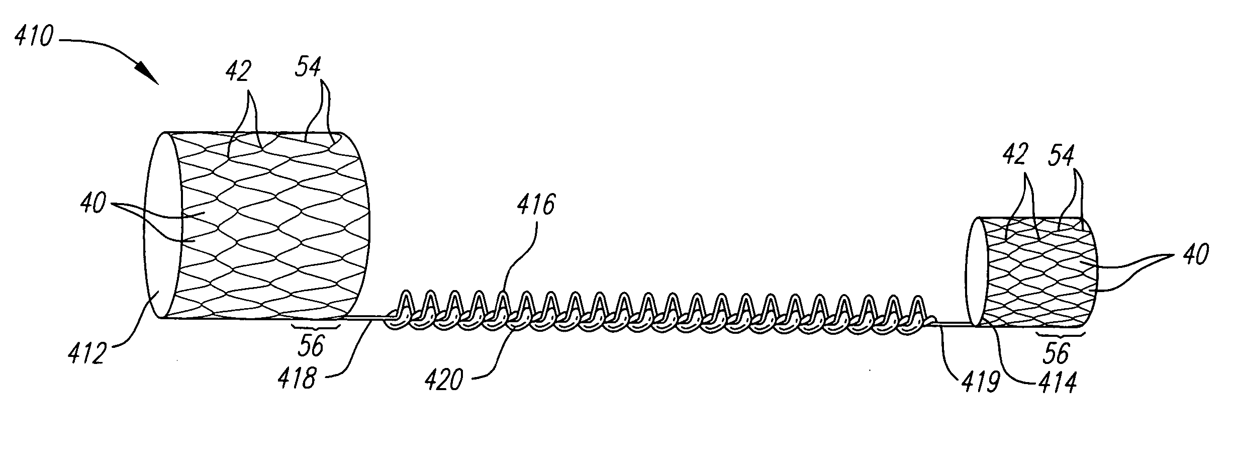
[0122] In that regard, the present invention, as shown in FIGS. 7 and 8, comprises a proximal stent module 200 (FIG. 8) and a distal stent module 205 (FIG. 7). Both the proximal and distal stent modules 200, 205 have a compressed and expanded state, as described above with respect to the previous embodiments.

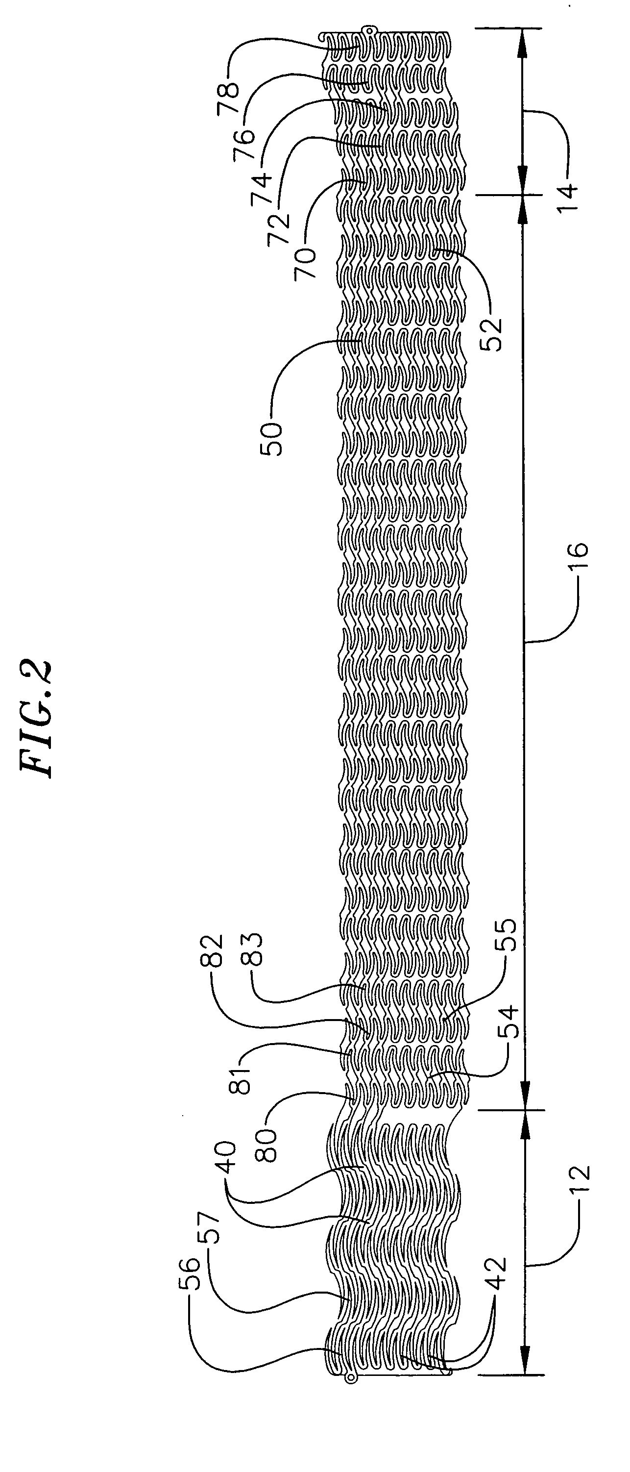
[0123] In one embodiment, the distal stent module 205 has an anchor section 214, located at the distal end of the distal stent module, and a central section 217. The anchor section 214 includes three loops. A first loop 270 is connected to a second loop 271 at four peaks 42 and the second loop is connected to a third loop 272 at two peaks. Accordingly, the distal stent module will be more flexible in the distal direction. The central stent section 217 includes thirty-six loops. As with respect to the first embodiment described above, alternating pairs of loops are connected at each peak to form rings of four-sided openings 40. Each ring is connected to an adjacent ring at three ...

second embodiment

[0124] As shown in FIG. 8, the proximal stent module 200 has an anchor section 212, located at the proximal end of the proximal stent module 200, and a central section 215. The anchor section 212 is a combination of the proximal stent section 112 and the proximal transitional section 118 as described above with respect to the The central section 215 includes twenty-four loops. Similarly to the central section 217 of the distal stent module 205, alternating pairs of loops are connected at each peak to form rings of four-sided openings 40. Each ring is connected to an adjacent ring at three peaks 42, where the connected portion forms a backbone 254 and the unconnected portion forms a severed region.

[0125] The device of the third embodiment is deployed as follows. The distal stent module 205 in a compressed state is mounted onto a first balloon (not shown), which acts as a delivery catheter. The first balloon has a length generally corresponding to the length of the anchor section 214...


PUM


Abstract

An elongate body including a proximal and distal anchor, and a bridge between the proximal and distal anchors. The bridge has an elongated state, having first axial length, and a shortened state, having a second axial length, wherein the second axial length is shorter than the first axial length. A resorbable thread may be woven into the bridge to hold the bridge in the elongated state and to delay the transfer of the bridge to the shortened state. In an additional embodiment, there may be one or more central anchors between the proximal and distal anchors with a bridge connecting adjacent anchors.

Description

CROSS-REFERENCE TO RELATED APPLICATION [0001] This application claims priority to and the benefit of U.S. Provisional Patent Application 60 / 530,352 filed Dec. 16, 2003 titled Device to Change the Shape of the Mitral Valve Annulus, U.S. Provisional Patent Application 60 / 547,741 filed Feb. 25, 2004 titled Methods and Apparatus for Treatment of Mitral Insufficiency, and U.S. Provisional Patent Application 60 / 624,224 filed Nov. 2, 2004 titled Device for Changing the Shape of the Mitral Annulus, the entire content of which is expressly incorporated herein by reference.FIELD OF THE INVENTION [0002] This invention relates to devices and methods for heart valve repair and, more particularly, to endovascular devices and methods for improving mitral valve function using devices inserted into he coronary sinus. BACKGROUND [0003] Heart valve regurgitation, or leakage from the outflow to the inflow side of a heart valve, is a common occurrence in patients with heart failure and a source of morbi...

Claims


Application Information

Patent Timeline
Patent Type & Authority Applications(United States)
IPC IPC(8): A61F2/24
CPCA61F2/2451
Inventor SOLEM, JAN OTTOKIMBLAD, PER OLANIELSEN, STEVANJOERGENSON, IBQUINT, BODOSEIBOLD, GERDOEPEN, RANDOLF VONHA, SUK-WOOECKERT, KARL-LUDWIGSCHRECK, STEFANFARIABI, SEPEHRCONZELMANN, TOMMY
Owner EDWARDS LIFESCIENCES AG
Why Eureka
Try Eureka