
Roadway-powered electric vehicle system having automatic guidance and demand-based dispatch features

a technology of electric vehicles and dispatch features, applied in the field of electric vehicles, can solve the problems of inability to provide the convenience and range of the ice automobile, the system is extremely expensive to acquire, build and maintain, and the externally-powered ev system is inconvenient to use, so as to facilitate passenger loading, unloading, seating and safety, and recoup the energy cos

Inactive Publication Date: 2005-08-18
ROSS HOWARD R
View PDF13 Cites 139 Cited by
  • Summary
  • Abstract
  • Description
  • Claims
  • Application Information

AI Technical Summary

Benefits of technology

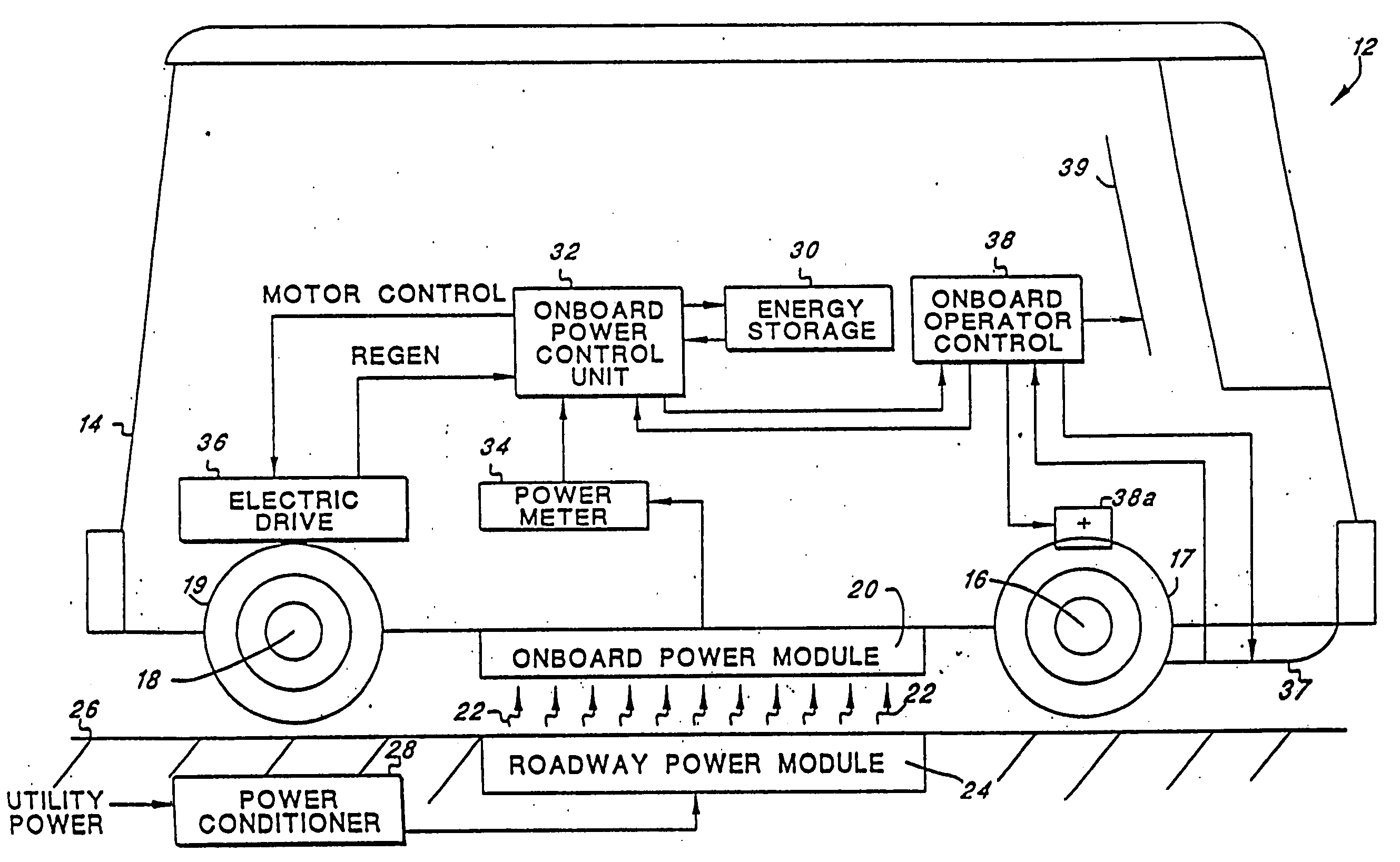
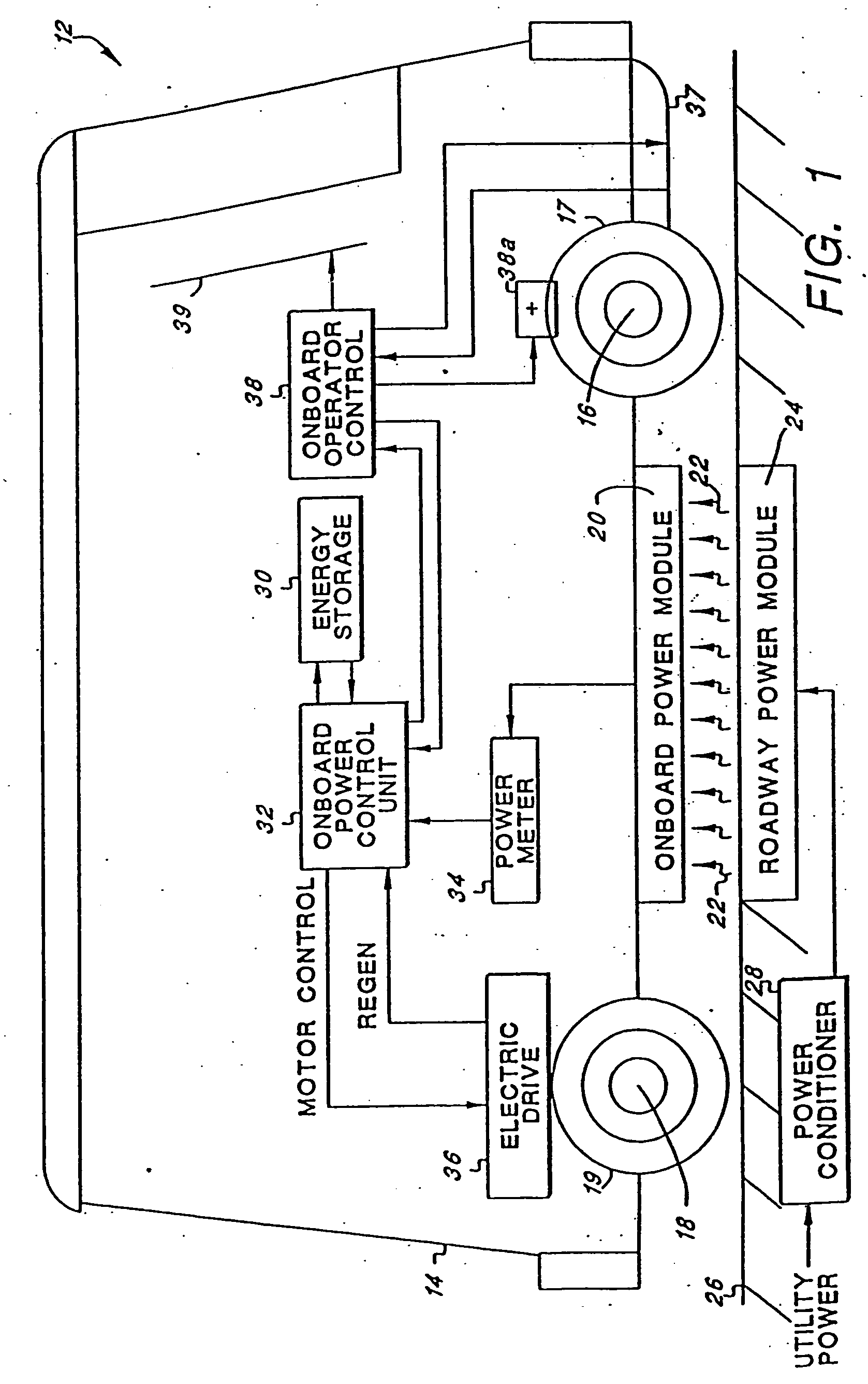
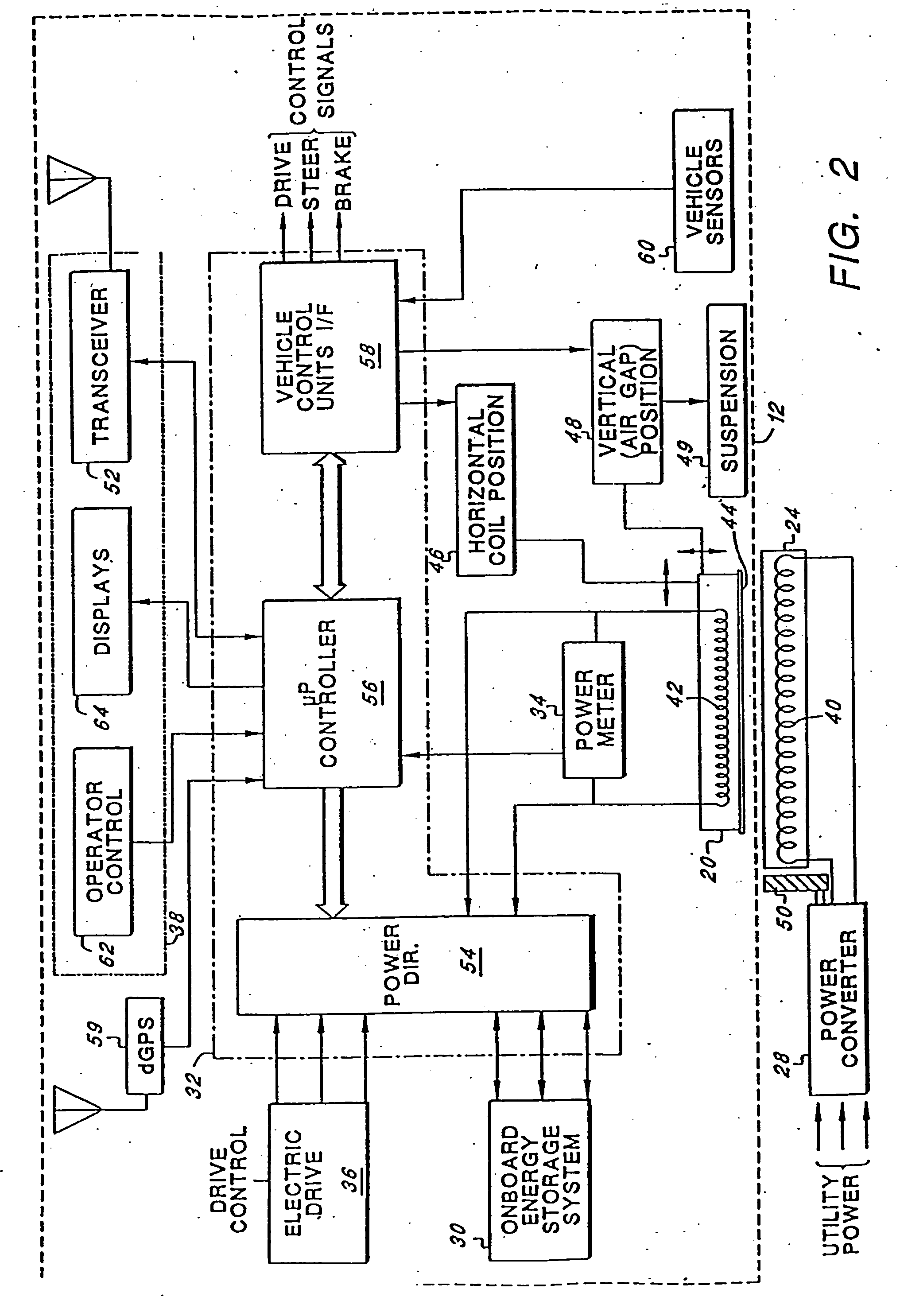
"The present invention is an improved roadway-powered electric vehicle system that includes an all-electric vehicle with an energy storage system. The energy storage system includes an embedded network of power coupling elements in the roadway that can be rapidly charged as the vehicle passes over them. The vehicle has onboard energy storage elements or devices that can be charged through a primary power source, such as a power conditioner, as the vehicle moves. The energy storage devices can be charged while the vehicle is in operation, as the power is converted from the electrical current. The vehicle's power controller monitors the power usage and the public utility can bill the vehicle for the energy used. The vehicle's energy storage system includes an electromechanical battery that can store and extract energy quickly, providing a significant improvement in energy density relative to conventional batteries. The battery is charged by simply applying an appropriate ac electrical signal to its terminals. The EMB functions as a motor / generator depending upon whether electrical energy is being applied or withdrawn. The high rotational speeds of the EMB allow for great amounts of energy to be stored and used to propel the vehicle."

Problems solved by technology

In contrast, vehicles that rely upon an internal combustion engine (ICE), in whole or in part, for their power source are continually fouling the air with their exhaust emissions.
However, such systems typically require their own highly specialized roadway, or right-of-way, system, as well as the need for an electrical energy source, such as a continuously electrified rail or overhead wire, with which the EV remains in constant contact.
These requirements make such systems extremely expensive to acquire, build and maintain.
Moreover, such externally-powered EV systems are not able to provide the convenience and range of the ICE automobile (which effectively allows its operator to drive any where there is a reasonable road on which the ICE vehicle can travel).
Unfortunately, however, such rechargeable battery-driven EV's have not yet proven to be economically viable nor practical.
For most vehicle applications, such rechargeable battery-driven EV's have not been able to store sufficient electrical energy to provide the vehicle with adequate range before needing to be recharged, and / or to allow the vehicle to travel at safe highway speeds for a sufficiently long period of time.
Disadvantageously, the energy density (i.e., the amount of energy that can be stored per unit volume) of currently-existing electrochemical batteries has been inadequate.
That is, when sufficient electrical storage capacity is provided on board the vehicle to provide adequate range, the number of batteries required to provide such storage capacity is prohibitively large, both in volume and weight.
Moreover, when such batteries need to be recharged, the time required to fully recharge the batteries is usually a number of hours, not minutes as most vehicle operators are accustomed to when they stop to refill their ICE vehicles with fuel.
Further, most currently-existing electrochemical batteries are not suited for numerous, repeated recharges, because such batteries, after a nominal number of recharges, must be replaced with new batteries, thereby significantly adding to the expense of operating the rechargeable battery-driven EV.
Disadvantageously, however, the use of such mechanical flywheel significantly complicates the drive system of the vehicle, and also significantly adds to the weight of the vehicle, thereby limiting its useful range between charges.
Further, the mechanical flywheel operating at fast speeds may present a safety hazard.

Method used


Image

  • Roadway-powered electric vehicle system having automatic guidance and demand-based dispatch features
  • Roadway-powered electric vehicle system having automatic guidance and demand-based dispatch features
  • Roadway-powered electric vehicle system having automatic guidance and demand-based dispatch features

Examples


Embodiment Construction

[0060] The following description is of the best mode presently contemplated for carrying out the invention. This description is not to be taken in a limiting sense, but is made merely for the purpose of describing the general principles of the invention. The scope of the invention should be determined with reference to the claims.

[0061] Broadly stated, the invention relates to a roadway-powered electric vehicle system that includes a network of highways and roadways that have been electrified at select locations, and a fleet of roadway-powered electric vehicles (RPEV's) that traverse the network of highways and roadways and receive their electrical operating power from the electrified highways and roadways. Many of the components that make up the RPEV system of the embodiments described herein are components that already exist and have been used for other types of EV systems, or other applications. Such components may be found, for example, and are described in the following docume...


PUM


Abstract

A roadway-powered electric vehicle (RPEV) system includes: (1) an all-electric vehicle; and (2) a roadway network over which the vehicle travels. The all-electric vehicle has one or more onboard energy storage elements or devices that can be rapidly charged or energized with energy obtained from an electrical current, such as a network of electromechanical batteries. The electric vehicle further includes an on-board controller that extracts energy from the energy storage elements, as needed, and converts such extracted energy to electrical power used to propel the electric vehicle. The energy storage elements may be charged while the vehicle is in operation. The charging occurs through a network of power coupling elements, e.g., coils, embedded in the roadway. The RPEV system also includes: (1) an onboard power meter; (2) a wide bandwidth communications channel to allow information signals to be sent to, and received from, the RPEV while it is in use; (3) automated garaging that couples power to the RPEV for both replenishing the onboard energy source and to bring the interior climate of the vehicle to a comfortable level before the driver and / or passengers get in; (4) electronic coupling between “master” and “salve” RPEV's in order to increase passenger capacity and electronic actuators for quick-response control of the “slave” RPEV; (5) inductive heating coils at passenger loading / unloading zones in order to increase passenger safety; (6) an ergonomically designed passenger compartment; (7) a locating system for determining the precise location of the RPEV; and (8) a scheduling and dispatch computer for controlling the scheduling of RPEV's around a route and dispatch of RPEV's based on demand.

Description

[0001] This application is a continuation of Ser. No. 10 / 097,531 filed Mar. 12 2002, which is a continuation of Ser. No. 09 / 538,455 filed May 30, 2000 which is a continuation of application Ser. No. 09 / 429 / 835, filed Oct. 29, 1999, which is a Continuation application of U.S. Ser. No. 09 / 290,033, filed Apr. 8, 1999, which is a Continuation application of U.S. Ser. No. 09 / 126,913, filed Jul. 30, 1998, which is a Continuation application of U.S. Ser. No. 08 / 934,477, filed Sep. 19, 1997, which is a Continuation-in-Part application of U.S. Ser. No. 08 / 238,990; filed May 5, 1994 for ROADWAY-POWERED ELECTRIC VEHICLE now U.S. Pat. No. 5,669,470; Issued Sep. 23 1997, all of which are incorporated herein by reference.BACKGROUND OF THE INVENTION [0002] The present invention relates to electric vehicles, and more particularly to an all-electric vehicle system that is powered from an onboard high-specific-power energy storage device, and that receives power to charge the energy-storage device in...

Claims


Application Information

Patent Timeline
Patent Type & Authority Applications(United States)
IPC IPC(8): B60L5/00B60L50/30G01S19/48
CPCB60L5/005Y02T90/121B60L11/16B60L11/1803B60L11/182B60L11/1831B60L2210/20B60L2230/16B60L2250/16B60L2270/32B60L2270/36Y02T10/7005Y02T10/7033Y02T10/7088Y02T10/725Y02T90/122Y02T90/127Y02T90/128Y02T90/14Y02T90/16Y02T90/163Y02T90/125B60L2200/26Y02T10/7027B60L7/14B60L50/30B60L50/51B60L53/124B60L53/126B60L53/305B60L53/39Y02T10/70Y02T10/7072Y02T10/72Y02T90/12
Inventor ROSS, HOWARD R.
Owner ROSS HOWARD R
Learn More