
Method and apparatus for drum level control for drum-type boilers

Inactive Publication Date: 2005-08-18
GENERAL ELECTRIC CO
View PDF18 Cites 29 Cited by
  • Summary
  • Abstract
  • Description
  • Claims
  • Application Information

AI Technical Summary

Benefits of technology

[0011] It will be appreciated that configurations of the present invention provide increased performance by allowing heat utilization systems of a power plant to provide higher efficiency. By providing intelligent drum level control, some configurations of the present invention provide a combination of smooth control during normal steady state operation as well as highly responsive control during condition of a process upset. Moreover, some configurations of the present invention also reduce the effects of erosion on feedwater control valves by reducing oscillations of the feedwater flow. Furthermore, by stabilizing flows in one drum, stabilization in other drums in a power plant is facilitated.

Problems solved by technology

Disruptions in service of drum type boilers can lead to loss of revenue as a result of reduced power generation from a power plant.
Further, disruptions in service can lead to reduced life of power plant components.
Drum level trips are the most common cause of trips and disruptions in a power station, especially from the Heat Recovery Steam Generator / Balance of (power) Plant (HRSG / BOP) area.
A trip of a plant stresses and reduces the life of power plant equipment and machinery.
If the steam turbine is a single-shaft configuration, the unit as a whole is tripped.
Oscillations in feedwater flow result in variation in the steam production from a drum.
In multi-drum or pressure boilers, systems are linked together so that disturbances and oscillations in one drum may cause disturbances in other drums.
This steaming causes fouling of the interior of the tubes in the economizer.
However, at low steam flows, the single element control mode is appropriate as flow conversions at the low end of the range are less accurate due to square root extraction from differential pressure transmitters used for measuring flows.
In addition, when the level deviation error remains high, the integral component increases with time to correct or trim the feedwater flow to correct the drum level.
However, the feedwater control tends to be oscillatory and can take a long time to settle down.

Method used


Image

  • Method and apparatus for drum level control for drum-type boilers
  • Method and apparatus for drum level control for drum-type boilers
  • Method and apparatus for drum level control for drum-type boilers

Examples


Embodiment Construction

[0017] The term “PID” as used herein is not limited to a proportional integral derivative control. Rather, the term “PID” is used herein to refer to a control selected from the group consisting of proportional controls, proportional plus integral controls, proportional plus derivative controls, and proportional integral derivative controls.

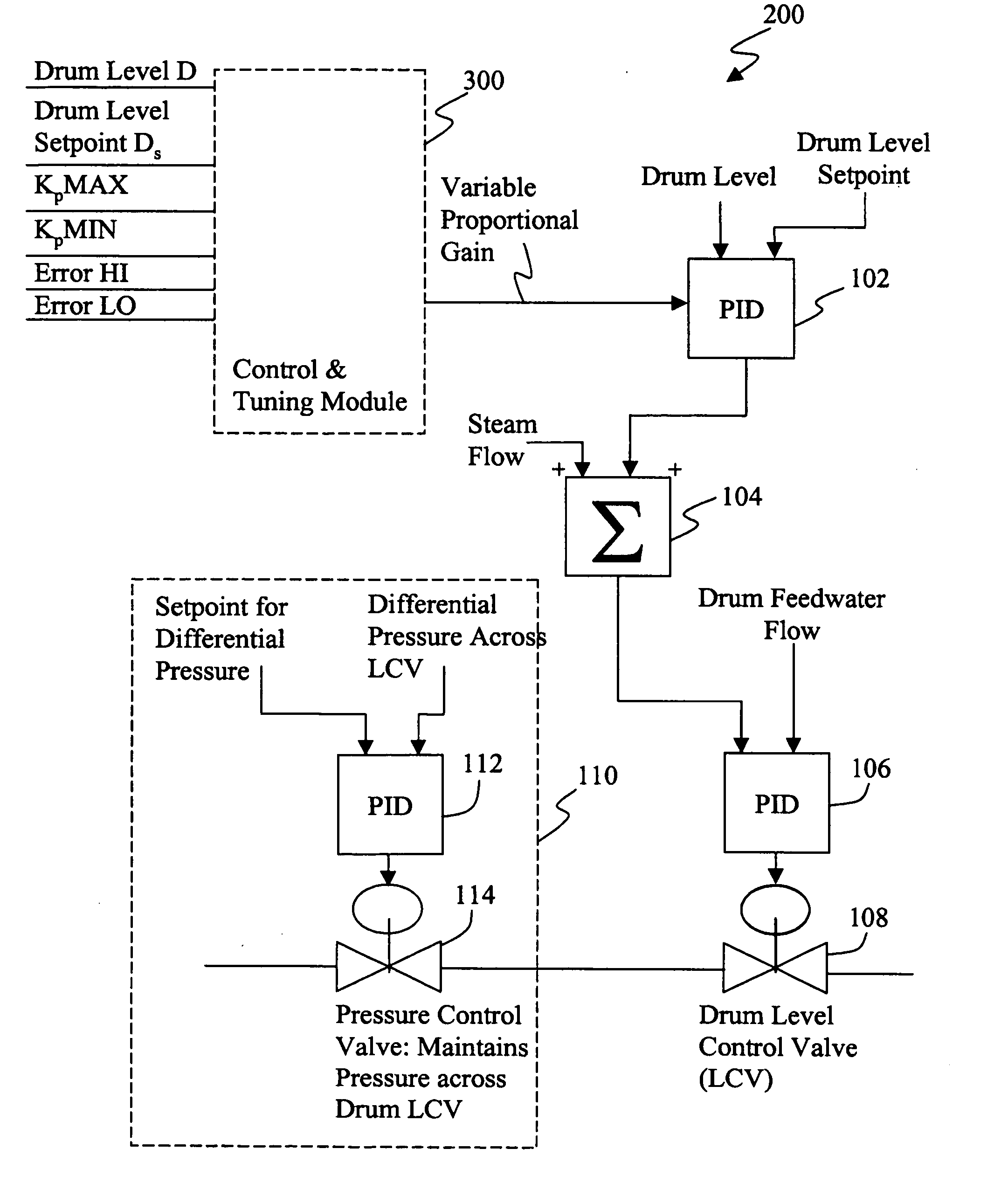
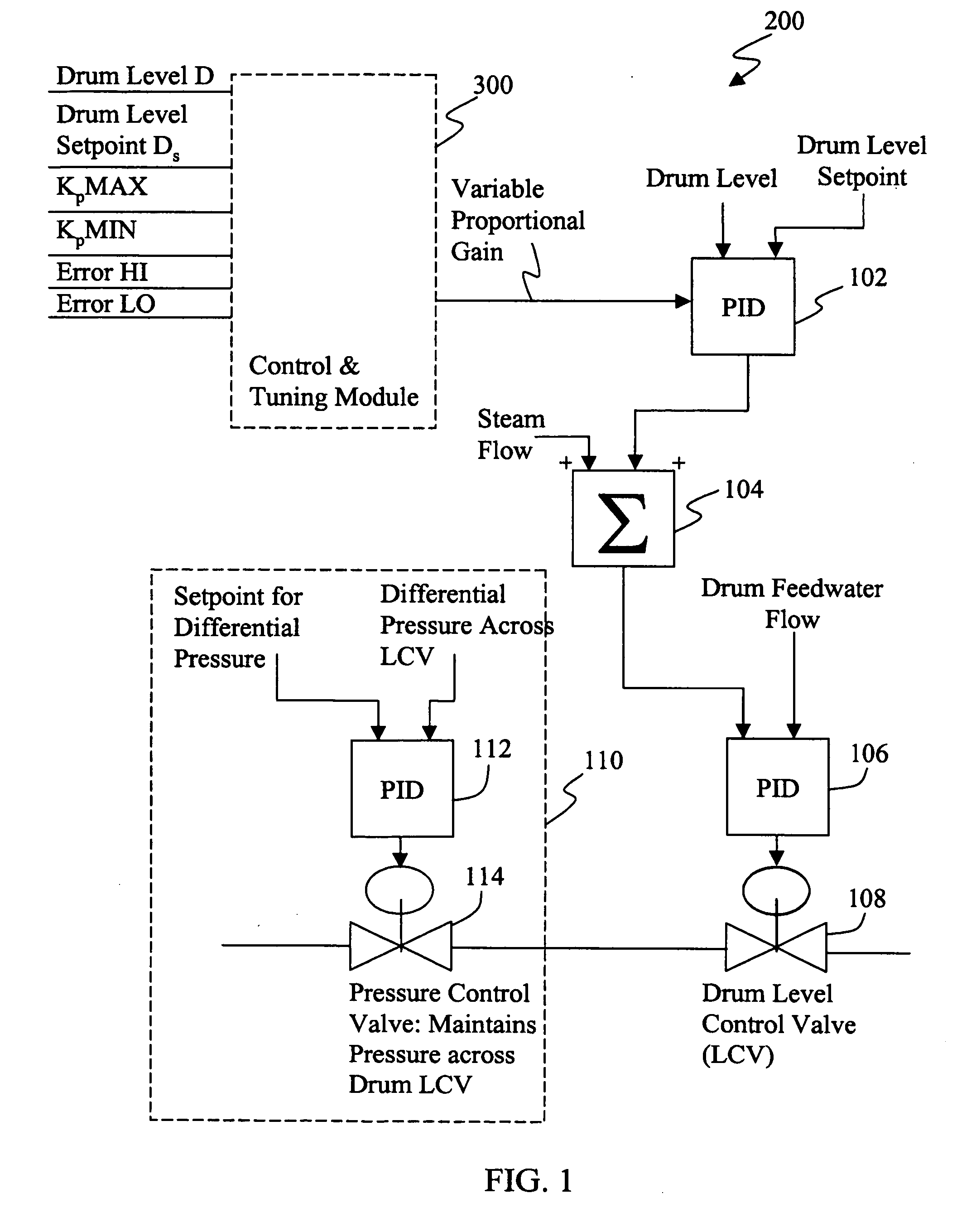
[0018] In some configurations of the present invention and referring to FIG. 1, a drum-type boiler control 200 is provided with a control and tuning module 300 that provides boiler tuning in both steady state conditions and in process upset conditions.

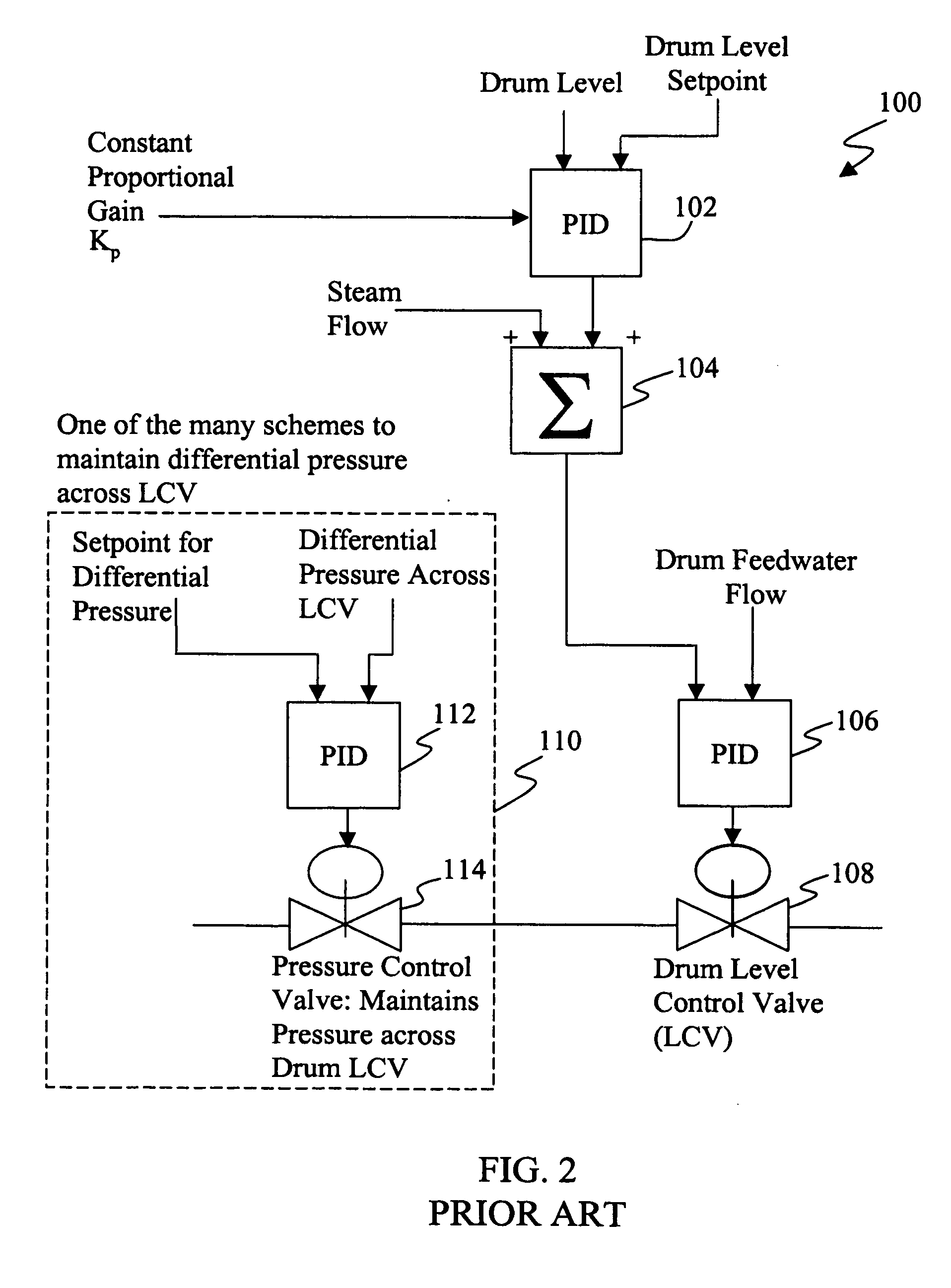
[0019] In a prior art three-element control system 100 represented in FIG. 2, drum level, feedwater flow, and steam flow are used as variables. A drum level PID control 102 uses a selected drum level setpoint, a signal representative of drum level, and a constant proportional gain Kp to provide an output that is summed with a signal representative of steam flow at summer 104 to provide a output tha...


PUM


Abstract

A method for controlling the level of a drum in a drum-type boiler includes adjusting a gain of a drum level PID (such as a Proportional Integral Derivative control) in accordance with a signal representative of a set of tuning constants, a signal representative of drum level, and a signal representative of a drum level setpoint. The method also includes utilizing a flow control PID to adjust a drum level control valve, wherein the flow control PID adjusts the drum level control valve in accordance with an output of the drum level PID, a signal representative of steam flow, and a signal representative of drum feedwater flow.

Description

BACKGROUND OF THE INVENTION [0001] This invention relates generally to methods and apparatus for enhancing performance of drum type boilers while reducing operational disruptions. [0002] Disruptions in service of drum type boilers can lead to loss of revenue as a result of reduced power generation from a power plant. Further, disruptions in service can lead to reduced life of power plant components. [0003] Drum level trips are the most common cause of trips and disruptions in a power station, especially from the Heat Recovery Steam Generator / Balance of (power) Plant (HRSG / BOP) area. A trip of a plant stresses and reduces the life of power plant equipment and machinery. [0004] Drum type boilers are the most commonly used boilers in power generation plants. There are two trips from a boiler drum level. The extremely high level trip is related to the safety of the steam turbine from the possibility of a water carry over. In the event of an extremely high level trip, the steam turbine i...

Claims


Application Information

Patent Timeline
IPC IPC(8): F22D5/30F01K23/10G05D9/12G05D16/20
CPCF01K23/101G05D16/2013Y02E20/16G05D16/028F22B35/00F22D5/30G05D9/12F22B35/18F22B37/42
Inventor ARORA, MANU DEVTOMLINSON, LEROY OMARSMITH, RAUB WARFIELDNORMAN, BRUCE GORDONLENNON, MATTHEW
Owner GENERAL ELECTRIC CO
Learn More