Composition, optical compensatory film and liquid crystal display

a liquid crystal display and film technology, applied in the field of liquid crystal display, can solve the problems of lowering display quality, difficult to optically compensate liquid crystal cells perfectly, and inability to avoid contrast inversions generating at under areas of images, etc., to achieve simple configuration, improve viewing angle, not only display quality

Active Publication Date: 2005-08-18
FUJIFILM CORP
View PDF4 Cites 16 Cited by
  • Summary
  • Abstract
  • Description
  • Claims
  • Application Information

AI Technical Summary

Benefits of technology

[0007] One object of the present invention is to provide an IPS mode liquid-crystal display, having a simple configuration, improved in not only displaying-quality but also viewing angle. Another object of the present invention is to provide an optical compensatory film contributing to improvement of viewing angle of a liquid-crystal display, especially an IPS-mode liquid-crystal display, and a composition useful for producing such an optical compensatory film.

Problems solved by technology

However, it is extremely difficult to optically compensate liquid-crystal cells perfectly even if liquid-crystal molecules are used, and it is not possible to avoid contrast inversions generating at under areas of images.
Consequently, small light leakage generating at opposing corners in an oblique direction in a black state has come to the surface as a cause of lowering displaying-quality.
Many of the proposed methods are methods to improve viewing angles by counteracting the birefringence of liquid crystal in the cell, and cannot sufficiently prevent light leakage generating while the liquid-crystal displays are observed in oblique direction and, thus, the polarizing axes are out of orthogonal alignment.
Some of the proposed methods are for lowering such light leakage and, however, even if such methods are employed, it is extremely difficult to optically compensate the liquid-crystal cell perfectly.
Known optical compensatory sheets used for an IPS mode liquid-crystal cell are thick since they consists of plural films, and this is disadvantageous for thinning of liquid-crystal displays.

Method used


Image

  • Composition, optical compensatory film and liquid crystal display
  • Composition, optical compensatory film and liquid crystal display
  • Composition, optical compensatory film and liquid crystal display

Examples


example 1

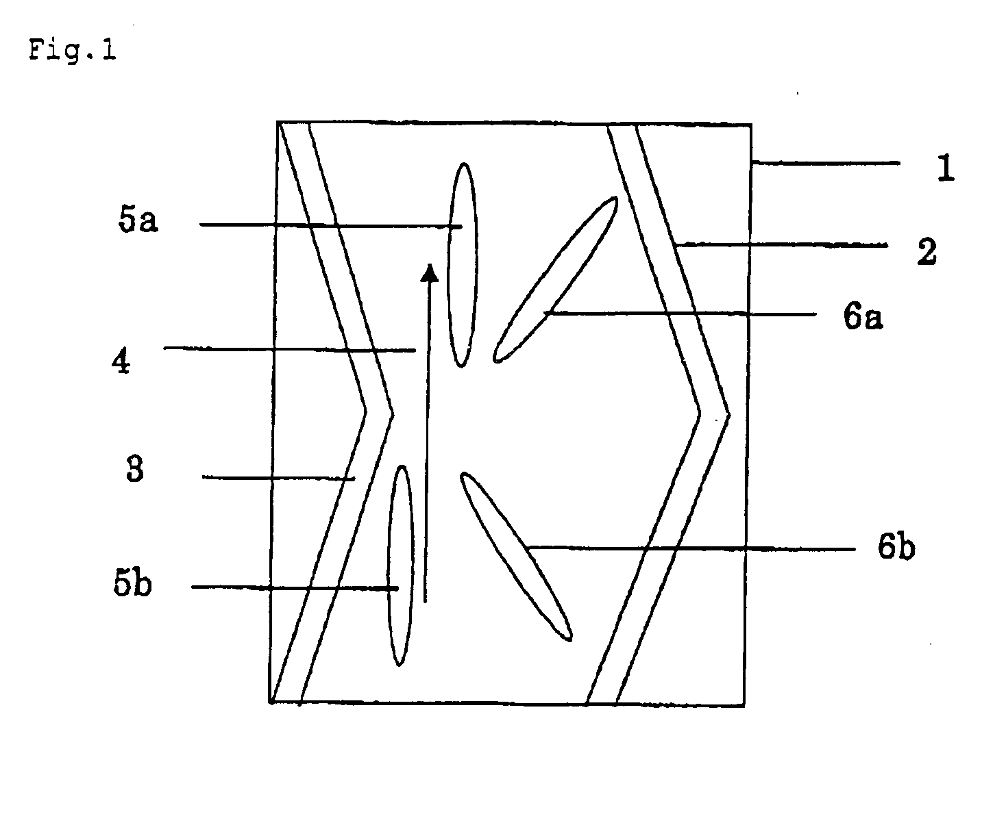
[0232] An electrode shown in FIG. 1 was formed on a glass plate so that the distance between the electrodes was 20 μm, and a polyimide film was formed on the electrode and subjected to rubbing treatment. The rubbing treatment was carried out in a direction shown in FIG. 1. A polyimide film was formed on another glass plate and subjected to rubbing treatment to form an alignment layer. Two such glass substrates were positioned with their alignment layers facing with their rubbing directions being parallel to each other and with a 3.9 micrometer gap between them. Nematic liquid-crystal composition, having a refractive-index anisotropy, Δn, of 0.0769 and a dielectric-constant anisotropy, Δe, of 4.5, was poured into the gap between the substrates to form a liquid-crystal layer. The d·Δn of the layer was 300 nm.

(Preparation of First Retardation Area)

[0233] The following components were charged to a mixing tank and stirred with heating to prepare a cellulose acetate solution (dope).

[0...

example no.2

Example No. 2

[0244] A commercially available cellulose acetate film (“FUJITAC TD80UF” manufactured by FUJI PHOTO FILM CO., LTD.), having a Re of 3 nm and a Rth of 45 nm, was used as a first retardation area. The film was saponified, and the coating liquid for an alignment layer, prepared in the same manner of Examples 1, was applied to the saponified surface with a wire-bar coater in an amount of 20 ml / m2, dried with hot air of 60° C. for 60 seconds, and subsequently dried with hot air of 100° C. for 120 seconds to form a polymer layer. Next, the polymer layer was subjected to rubbing treatment in a direction parallel to the slow axis of the film to form an alignment layer.

[0245] Subsequently, a coating solution was prepared in the same manner of Example 1, or in other words prepared by dissolving 1.8 g of a liquid-crystal compound shown above, 0.2 g of ethylene oxide-modified trimethyrol propane triacrylate (V#360 made by Osaka Organic Chemicals (Ltd.), 0.06 g of a polymerization ...

example 3

[0250] A commercially available cellulose acetate film (“FUJITAC TD80UF” manufactured by FUJI PHOTO FILM CO., LTD.), having a Re of 3 nm and a Rth of 45 nm, was saponified, and a coating liquid, which was prepared by diluting a commercially available vertical alignment layer (“JALS-204R” manufactured by JSR Corporation) with methyl ethyl ketone in a ratio of 1:1, was applied to a saponified surface of the cellulose acetate film with a wire-bar coater in an amount of 2.4 ml / m2; and immediately, dried with hot air of 120° C. for 120 seconds.

(Preparation a Layer in Which Rod-Like Liquid-Crystal Molecules are Aligned Vertically)

[0251] A coating solution was prepared by dissolving 1.8 g of a liquid-crystal compound shown below, 0.06 g of a polymerization initiator (IRGACURE 907 manufactured by Ciba-Geigy), 0.02 g of a sensitizer (KAYACURE-DETX manufactured by NIPPON KAYAKU CO., LTD.) and 0.002 g of a vertical alignment agent at an air-interface sown below in 9.2 g of methyl ethyl keto...


PUM

PropertyMeasurementUnit
angleaaaaaaaaaa
angleaaaaaaaaaa
angleaaaaaaaaaa

Abstract

A composition comprising at least one compound having a fluoro-aliphatic group and at least one hydrophilic group selected from the group consisting of a carboxyl group (—COOH), a sulfo group (—SO3H), a sulfato group (—OSO3H), a phosphonoxy group {—OP(═O)(OH)2} and salts thereof; at least one onium salt; and at least one liquid-crystal compound is disclosed.

Description

CROSS-REFERENCE TO RELATED APPLICATIONS [0001] This application claims benefit of priority under 35 USC 119 to Japanese Patent Application No. 2004-003802 filed Jan. 9, 2004. TECHNICAL FIELD [0002] The present invention relates to a liquid crystal display, and especially to an in-plane-switching (IPS) mode display which displays images by applying the crosswise field to liquid-crystal molecules aligned homogenously. The present invention also relates to an optical compensatory film or a composition useful for preparing the film. RELATED ART [0003] TN-mode liquid-crystal displays have been used widely. The TN-mode DLC usually comprises two polarizing plates and a liquid-crystal layer formed of twisted-orientated nematic liquid crystal sandwiched in between the polarizing plates, and the field is applied in an orthogonal direction to the substrate of the liquid-crystal layer. In the TN-mode, liquid-crystal molecules tilt against the substrate in a black state, and thus, birefringence ...

Claims


Application Information

Patent Timeline
Patent Type & Authority Applications(United States)
IPC IPC(8): C08L101/02C09K19/34C09K19/54C09K19/58G02F1/13G02B5/30G02F1/13363G02F1/1337G02F1/1343
CPCC09K19/3444C09K19/54C09K19/542C09K19/582C09K2019/328G02F1/133632Y10T428/1086G02F1/134363Y10T428/1036Y10T428/1041Y10T428/1059Y10T428/10G02F1/133784C09K2323/031C09K2323/05C09K2323/06C09K2323/03C09K2323/00
Inventor MORISHIMA, SHINICHINIMURA, SHIGEAKI
Owner FUJIFILM CORP
Why Eureka
Try Eureka