Mold temperature adjusting apparatus/method and mold temperature control unit

a mold temperature and adjusting apparatus technology, applied in the field of mold temperature, can solve the problems of insufficient transfer of molten resin onto the cavity surface of the mold, the surface of the molded object often becomes coarse, and the solidification of resin, etc., to achieve the effect of reducing the heat transmission of the fluid of low temperature from the fluid of high temperature, reducing the mixing of fluids, and saving energy

Inactive Publication Date: 2005-08-18
MITSUBISHI HEAVY IND LTD
View PDF12 Cites 27 Cited by
  • Summary
  • Abstract
  • Description
  • Claims
  • Application Information

AI Technical Summary

Benefits of technology

[0042] As the invention of claim 4 employs the above-mentioned fourth means, the boundary surface area of the boundary generated by the specific gravity difference between the fluid of high temperature and the fluid of low temperature is separated into small units by the rectifying plates. Hence, in addition to the effect of the invention of claim 2, mixing of the fluids can be further reduced.
[0043] As the invention of claim 5 employs the above-mentioned fifth means, in addition to the effect of the invention of claim 5, the fluid of high temperature and the fluid of low temperature can be completely partitioned from each other by the float disc, and heat transmission to the fluid of low temperature from the fluid of high temperature can be reduced.
[0044] As the invention of claim 6 employs the above-mentioned sixth means, in addition to the effect of the invention of claim 5, the float disc is made in the form of the bag filled with the fluid and the float disc can be securely floated in the boundary between the fluid of high temperature and the fluid of low temperature.
[0045] As the invention of claim 7 employs the above-mentioned seventh means, in addition to the effect of the invention of any one of the second to the sixth means, heat escaping from the fluid of high temperature through a wall of the heat recovery tank can be reduced and an energy saving effect can be obtained.
[0046] As the invention of claim 8 employs the above-mentioned eighth means, each change-over of the fluids is performed earlier by the time needed for elevation of the heating over-shooting temperature as well as by the time needed for lowering of the cooling under-shooting temperature. Thereby, the time of the molding steps can be shortened. Also, the fluid of high temperature and the fluid of low temperature are alternately replaced with each other in the single heat recovery tank. Hence, the facilities can be simplified and the heat loss of the fluid as a heat medium can be reduced.
[0047] As the invention of claim 9 employs the above-mentioned ninth means, with respect to both of the fluid of high temperature and the fluid of low temperature, the temperature of the most part of the supply pipings and return pipings can be maintained constant. Thus, in addition to the effect of the invention of claim 8, the heat loss becomes less and the recovery effect of the fluid or heat medium becomes large. Also, frequent starts and stops of the pumps are not needed so that the operation becomes smooth and the mechanical durability is enhanced.

Problems solved by technology

In an injection step of an injection molding machine, if a mold temperature is low, a molten resin that is injected makes contact with the mold while pressure in the mold is not elevated yet, so that a resin surface rapidly solidifies and a surface of a molded article often becomes coarse.
This is liable to cause a problem that the molten resin is not sufficiently transferred onto a cavity surface of the mold.
Hence, the temperature is considerably reduced by a radiation and when this high temperature medium is returned into the high temperature medium passage, it is mixed with a high temperature medium of which temperature has been adjusted to an appropriate high temperature and there arises a problem that the temperature is reduced.
Thus, when this recovered high temperature fluid is recovered into the high temperature fluid passage system, the temperature of the high temperature fluid is reduced and there arises a problem that the high temperature fluid is to be re-heated in the high temperature fluid passage system so that a temperature adjustment is carried out.

Method used


Image

  • Mold temperature adjusting apparatus/method and mold temperature control unit
  • Mold temperature adjusting apparatus/method and mold temperature control unit
  • Mold temperature adjusting apparatus/method and mold temperature control unit

Examples


first embodiment

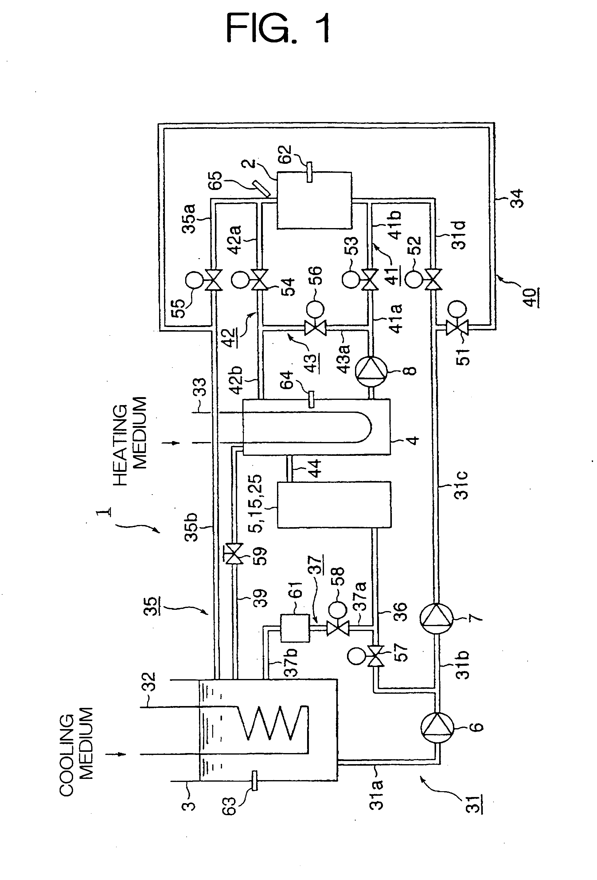
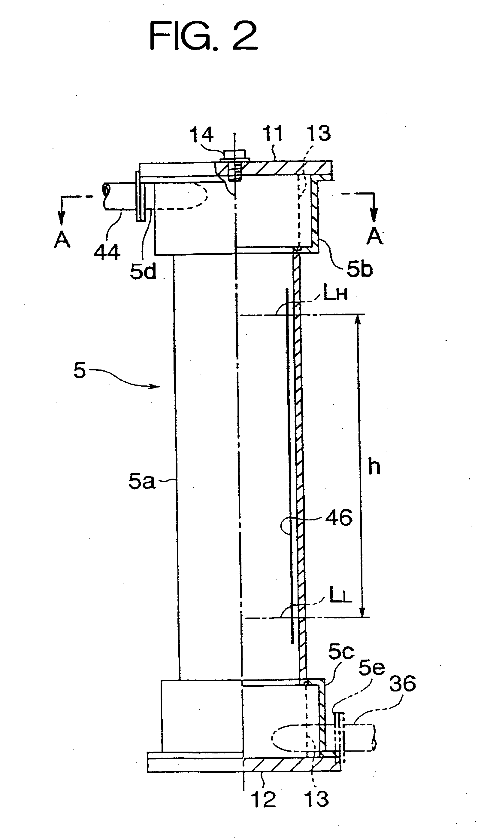
[0073]FIG. 1 is a schematic piping diagram of a mold temperature adjusting apparatus of a molding machine of a first embodiment according to the present invention, FIG. 2 is a partially cross sectional side view showing a first example of a concrete construction of a heat recovery tank of the mold temperature adjusting apparatus of the present first embodiment, FIG. 3 is a cross sectional view taken on line A-A of FIG. 2 and FIG. 4 is an enlarged partial view showing a hole arrangement of a multi-hole plate of the heat recovery tank of FIG. 2.

[0074]FIG. 5 is a cross sectional side view showing a second example of the concrete construction of the heat recovery tank of the mold temperature adjusting apparatus of the present first embodiment, FIG. 6 is a view showing one example of a cross sectional view taken on line B-B of FIG. 5 and FIG. 7 is a view showing another example of the cross sectional view taken on line B-B of FIG. 5.

[0075]FIG. 8 is a cross sectional side view showing a...

second embodiment

[0171] Next, a mold temperature adjusting apparatus of a second embodiment according to the present invention will be described with reference to FIGS. 14 to 17. Also, a mold temperature adjusting method with respect to this second embodiment will be described.

[0172] In the present second embodiment, as compared with the first embodiment as described above, there are provided neither the low temperature water by-pass system 40 nor the high temperature water by-pass system 43, but the heat medium is likewise controlled such that opening and closing of each of the valves are effected as well as start and stop of the high temperature water transfer pump 8 are carried out. Nevertheless, the construction may also be made such that the low temperature water by-pass system 40 and the high temperature water by-pass system 43 are provided being connected to the mold temperature adjusting apparatus, like in the first embodiment, to thereby control the flow of the heat medium by opening and c...

third embodiment

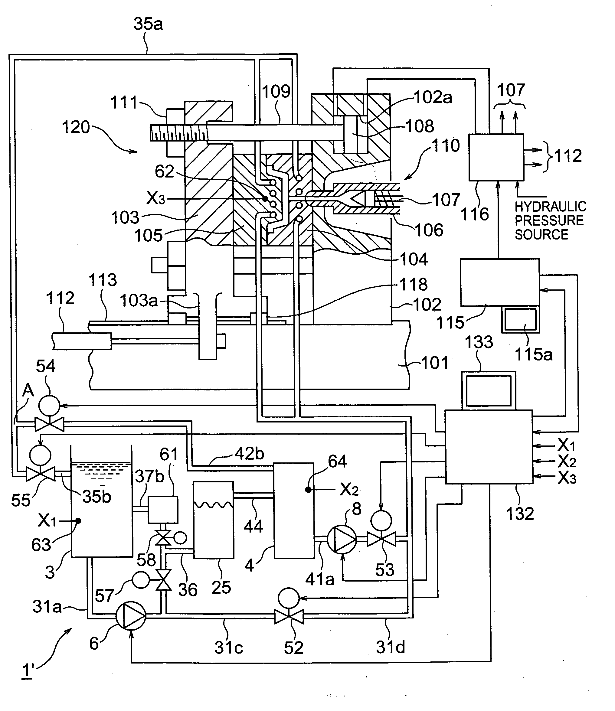
[0236] Next, a third embodiment of a mold temperature adjusting apparatus 1″ and method according to the present invention will be described with reference to FIGS. 18 and 19.

[0237] The present third embodiment is substantially the same as the second embodiment except that the injection molding condition setting and image displaying panel 133 and setting means 146 shown in FIGS. 14 and 15 are eliminated and their functions are taken charge of by the setting and displaying means 115a.

[0238] That is, the setting and displaying means 115a comprises an image displaying panel of touch key type as shown in FIG. 16, on which the image of FIG. 16 is displayed when a first display mode is set by operation of touch keys or the like.

[0239] In this case, the mold temperature set positions, timer operation start positions, etc. in the molding steps, as mentioned above, can be specified by touch keys and set values of temperature, time, etc. corresponding to the positions so specified can be i...


PUM

PropertyMeasurementUnit
Riaaaaaaaaaa
temperatureaaaaaaaaaa

Abstract

A mold temperature adjusting apparatus is provided in which change-over timing of high temperature medium and low temperature medium is adjusted by a heat transmission delay in heating and cooling of a mold being taken into consideration, so that a cycle time of molding steps is shortened, a temperature deflection from a set temperature of the high temperature and low temperature medium is reduced, an energy loss is reduced and an optimal mold temperature for an injection step can be obtained. The mold temperature adjusting apparatus comprises a high temperature fluid tank and a low temperature fluid tank, a high temperature fluid supply system and a high temperature fluid return system between the mold and the high temperature fluid tank, a low temperature fluid supply system and a low temperature fluid return system between the mold and the low temperature fluid tank, a high temperature fluid by-pass system and a low temperature fluid by-pass system, a heat recovery tank connected to the high temperature fluid tank and a pressure adjusting means.

Description

BACKGROUND OF THE INVENTION [0001] 1. Field of the Invention [0002] The present invention relates to a mold temperature adjusting apparatus and method by which a change-over timing between a high temperature medium and a low temperature medium is appropriately adjusted so as to shorten a molding cycle time. The present invention also relates to a mold temperature control unit of the same concept. [0003] 2. Description of the Related Art [0004] In an injection step of an injection molding machine, if a mold temperature is low, a molten resin that is injected makes contact with the mold while pressure in the mold is not elevated yet, so that a resin surface rapidly solidifies and a surface of a molded article often becomes coarse. This is liable to cause a problem that the molten resin is not sufficiently transferred onto a cavity surface of the mold. In order to avoid this problem, it is necessary to elevate the mold temperature so that solidification of the surface of the molten res...

Claims


Application Information

Patent Timeline
Patent Type & Authority Applications(United States)
IPC IPC(8): B29C45/73B29C33/04B29C35/00G05D23/02
CPCB29C35/007B29C2045/7393B29C45/7306Y02P70/10E04G11/02E04G25/061E04G2025/045
Inventor MURANAKA, OSAMUTODA, NAOKIBESSHO, MASAHIROMIYAGAWA, SATOSHIKUBOTA, KOJI
Owner MITSUBISHI HEAVY IND LTD
Why Eureka
Try Eureka