
Discharge lamp ballast circuit

a ballast circuit and discharge lamp technology, applied in the direction of electric variable regulation, process and machine control, instruments, etc., can solve the problems of reducing the yield and cost of components, hindering the reduction of size and cost, and shortening the life of discharge lamps, so as to reduce the size and cost of the ballast circuit, and prolong the life of the discharge lamp

Inactive Publication Date: 2005-08-18
MITSUBISHI ELECTRIC CORP
View PDF3 Cites 14 Cited by
  • Summary
  • Abstract
  • Description
  • Claims
  • Application Information

AI Technical Summary

Benefits of technology

[0014] The present invention is implemented to solve the foregoing problems. It is therefore an object of the present invention to provide a discharge lamp ballast circuit capable of increasing the life of a discharge lamp, and of reducing the size and cost of the ballast circuit.
[0016] According to the present invention, the discharge lamp ballast circuit is configured such that it generates from the AC voltage boosted by the inverter the DC voltage higher than the breakdown voltage of the discharge lamp, or the superimposed voltage in which the pulsating component is superimposed on the DC voltage, and supplies the discharge lamp with one of the DC voltage and the superimposed voltage to start discharge. Thus, it offers an advantage of being able to lengthen the life of the discharge lamp, and to reduce the size and cost of the ballast circuit.

Problems solved by technology

However, since it must apply the high voltage every time to start the HID lamps, it has a problem of wearing the electrodes of the HID lamps by sputtering, and hence shortening their life.
This presents a problem of hindering reduction in size and cost.
Furthermore, to achieve the start of the HID lamps without fail at the first attempt, it is necessary to use a highly reliable spark gap, which prevents an increase in yields and reduction in cost of the component.

Method used


Image

  • Discharge lamp ballast circuit
  • Discharge lamp ballast circuit
  • Discharge lamp ballast circuit

Examples


embodiment 1

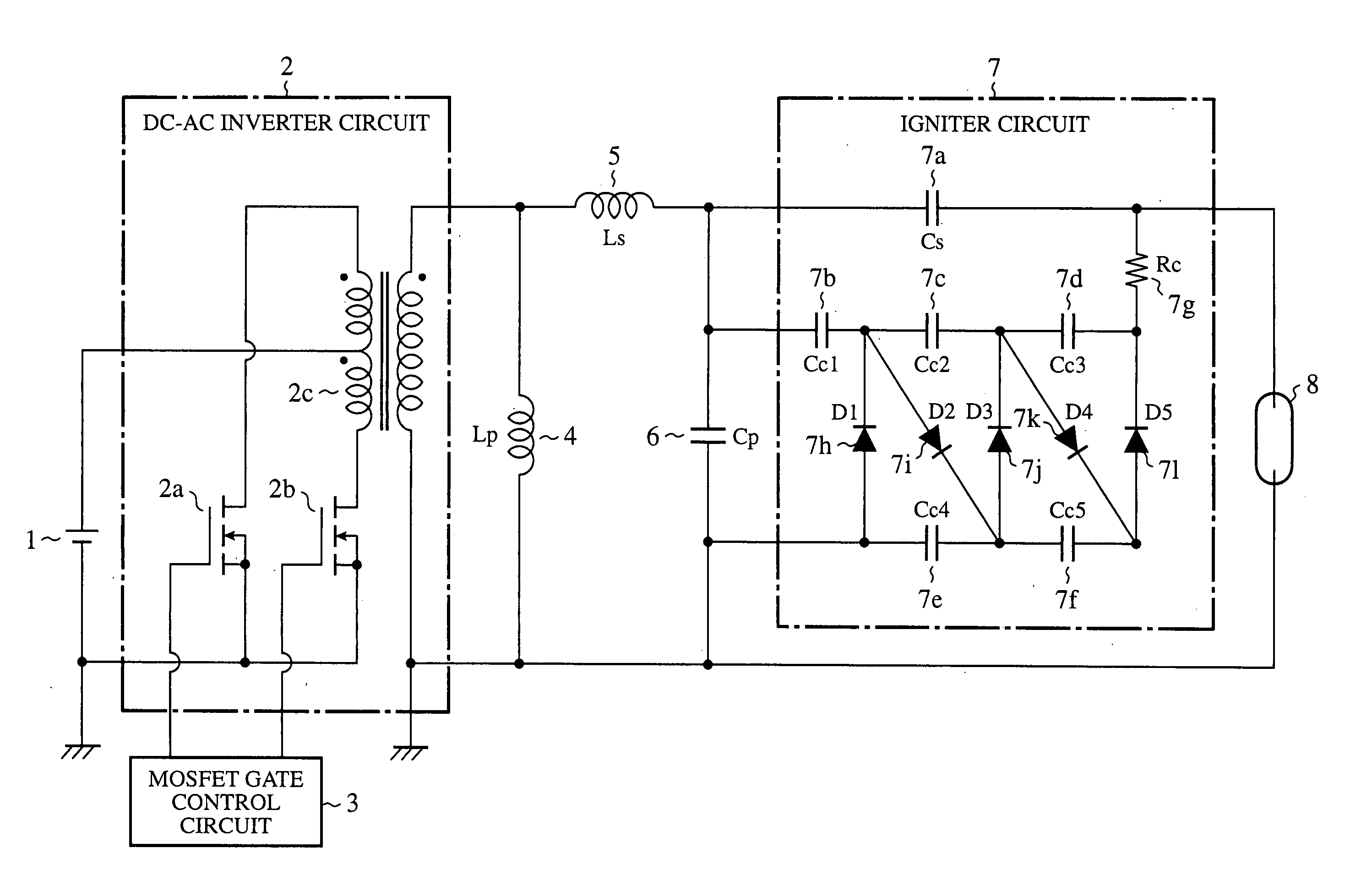
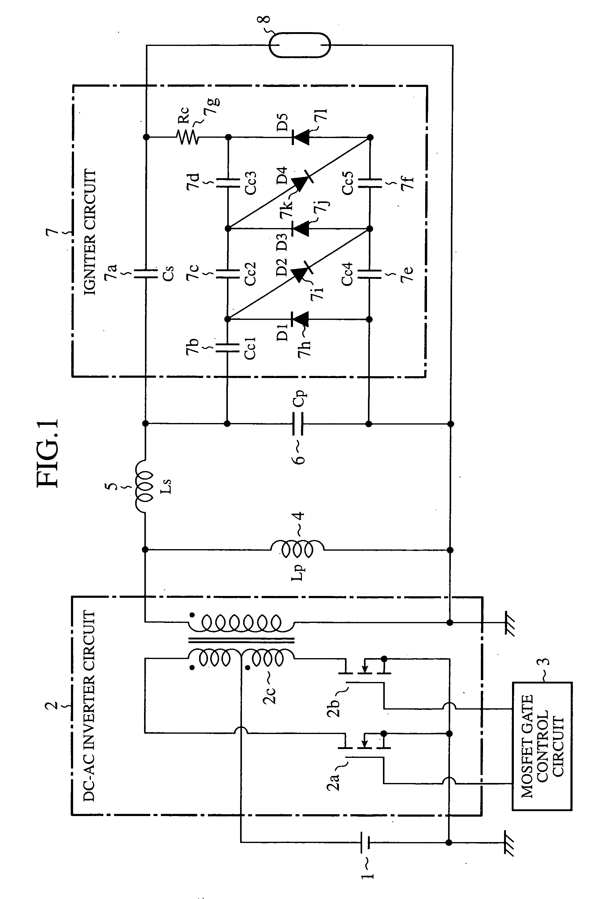
[0026]FIG. 1 is a circuit diagram showing a configuration of a discharge lamp ballast circuit of an embodiment 1 in accordance with the present invention. In FIG. 1, a DC power supply 1 generates a DC voltage of 12 volts, for example, and has its minus potential side connected to a ground.

[0027] ADC-AC inverter circuit (inverter) 2 converts the DC voltage generated by the DC power supply 1 to an AC voltage, and boosts the AC voltage. The DC-AC inverter circuit 2 includes MOSFETs 2a and 2b which are switching devices configured in a half bridge, and a pulse transformer 2c with a turn ratio of 1:23, for example.

[0028] A MOSFET gate control circuit 3 controls the operation frequency and duty of the MOSFETs 2a and 2b in the DC-AC inverter circuit 2 in response to the state of an HID lamp 8.

[0029] A reactor 4, a first reactor (called “reactor Lp” from now on), is connected in parallel with the secondary side of the pulse transformer 2c in the DC-AC inverter circuit 2. A reactor 5, a s...

embodiment 2

[0083] Although the foregoing embodiment 1 is described by giving concrete values of the constants of the components, it is obvious that any other constants can be used as long as a similar operation is performed.

[0084] In addition, although the foregoing embodiment 1 is described by way of example in which the HID lamp 8 is a vehicle-mounted metal halide lamp with a rating of 35 W, it is obvious that the present invention is applicable to the HID lamp 8 with a different rating.

[0085] Furthermore, although the igniter circuit 7 including the Cockcroft-Walton circuit is used as a means for generating the DC voltage, it is obvious that other circuits can be used to produce the DC voltage.

embodiment 3

[0086]FIG. 7 is a circuit diagram showing a configuration of a discharge lamp ballast circuit of an embodiment 3 in accordance with the present invention. In FIG. 7, the same reference numerals designate the same or like portions to those of FIG. 1, and their description will be omitted here.

[0087] A reactor 9, a first reactor (called “reactor Ls1” from now on), has its first end connected to a first output end of the secondary side of the pulse transformer 2c in the DC-AC inverter circuit 2.

[0088] A reactor 10, a second reactor (called “reactor Ls2” from now on), has its first end connected to the second end of the capacitor Cp, and its second end connected to the second end of the HID lamp 8.

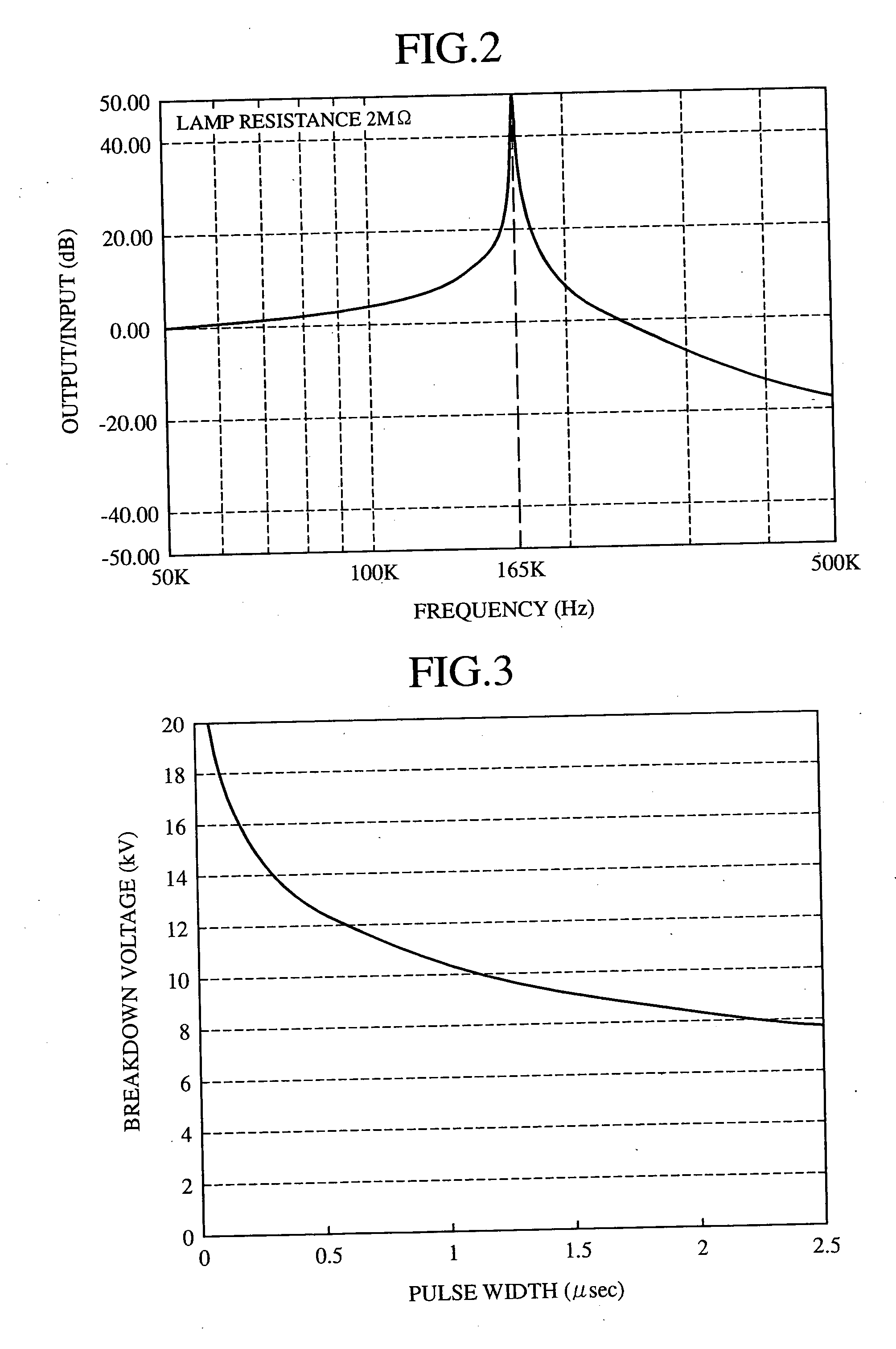
[0089]FIG. 8 is a graph illustrating resonance characteristics of the embodiment 3 in accordance with the present invention. It differs from the foregoing embodiment 1 in that it does not use the parallel resonance. More specifically, it has the 1-mH reactor Ls2 connected in series with the...


PUM


Abstract

A discharge lamp ballast circuit is provided which can prolong the life of a discharge lamp, and reduce the size and cost of the ballast circuit. It generates from an AC voltage boosted by a DC-AC inverter circuit a DC voltage higher than the breakdown voltage of an HID lamp, or a superimposed voltage in which a pulsating component is superimposed on the DC voltage, and starts the discharge by applying the DC voltage or the superimposed voltage to the HID lamp. It can make the life of the HID lamp longer than that of the case where a high voltage short pulse is applied to the HID lamp.

Description

BACKGROUND OF THE INVENTION [0001] 1. Field of the Invention [0002] The present invention relates to a discharge lamp ballast circuit for controlling lighting of a discharge lamp such as an HID (High Intensity Discharge) Lamp. [0003] 2. Description of Related Art [0004] It is necessary for vehicle-mounted HID lamps, for example, to produce a breakdown by applying a short pulse voltage of about 20 kV to start a discharge. [0005] As for a conventional discharge lamp ballast circuit, a built-in igniter generates a high short pulse voltage, and supplies it to the HID lamps. [0006] The built-in igniter of the conventional discharge lamp ballast circuit has the following configuration. [0007] Specifically, when the voltage across a capacitor connected in parallel with a spark gap exceeds the on-voltage of the spark gap, the spark gap is turned on. [0008] Thus, a pulse current flows through the primary winding of an igniter transformer, which produces a short high voltage pulse of about 20...

Claims


Application Information

Patent Timeline
Patent Type & Authority Applications(United States)
IPC IPC(8): H05B41/288H05B41/38
CPCH05B41/2881Y02B20/204H05B41/388Y02B20/00
Inventor HARADA, SHIGEKIIZUMI, KIKUOIWATA, AKIHIKO
Owner MITSUBISHI ELECTRIC CORP
Learn More