Test tube holder

a technology for test tubes and holder plates, applied in supporting devices, instruments, ways, etc., can solve the problems of troublesome further maintenance, poor assembly workability, increased manufacturing costs, etc., and achieve the effect of improving assembly workability and durability of test tube holders and simplifying the structure of test tube holders

Inactive Publication Date: 2005-08-18
IDS CO LTD
View PDF2 Cites 18 Cited by
  • Summary
  • Abstract
  • Description
  • Claims
  • Application Information

AI Technical Summary

Benefits of technology

[0009] An object of the present invention is to simplify the structure of a test tube holder to thereby improve the assembly workability and durability of the test tube holder.

Problems solved by technology

Therefore, its assembly workability is poor, manufacturing costs may be increased, and further maintenance is troublesome when the O-ring has damaged.

Method used


Image

  • Test tube holder
  • Test tube holder
  • Test tube holder

Examples


Embodiment Construction

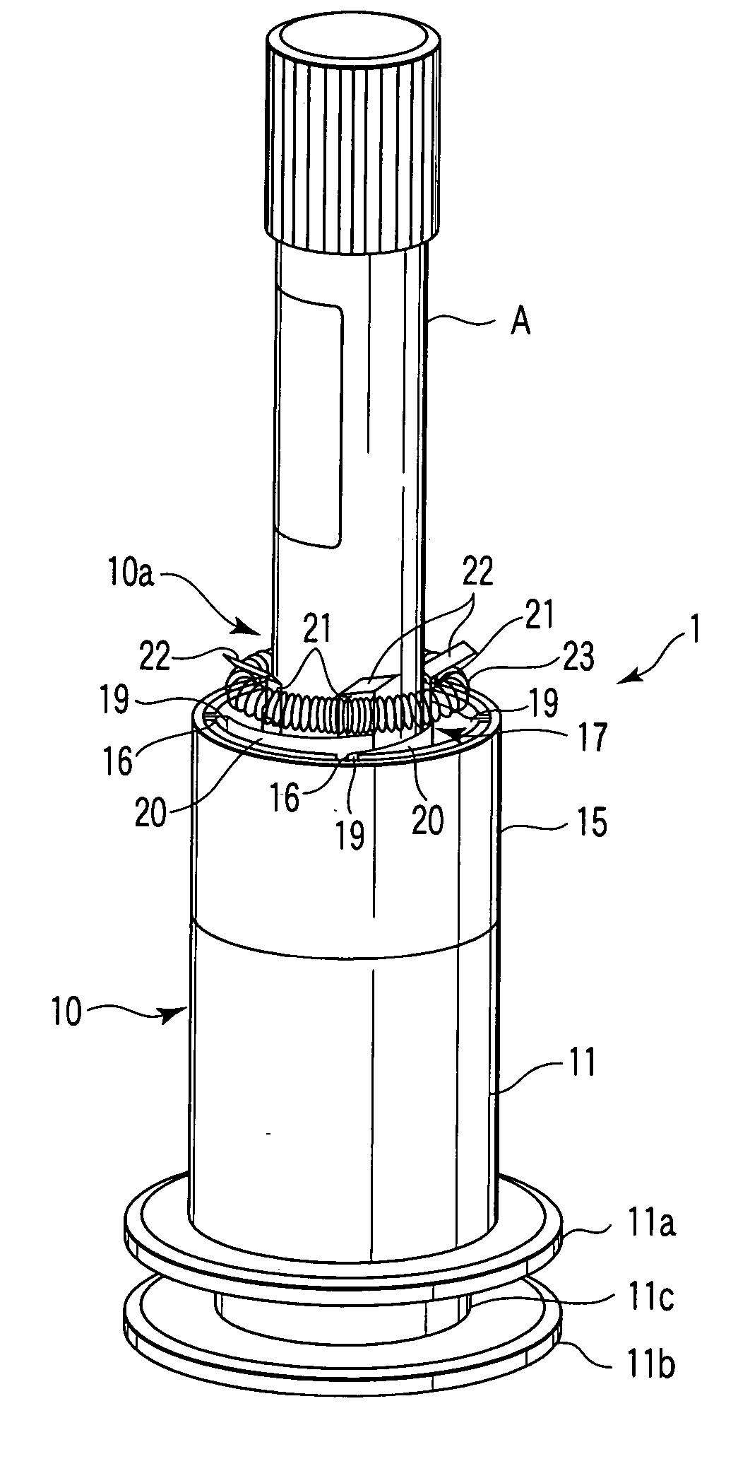
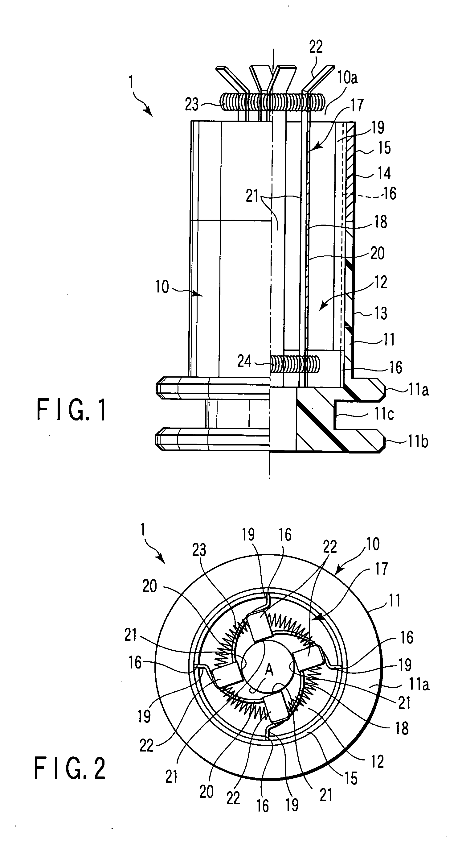
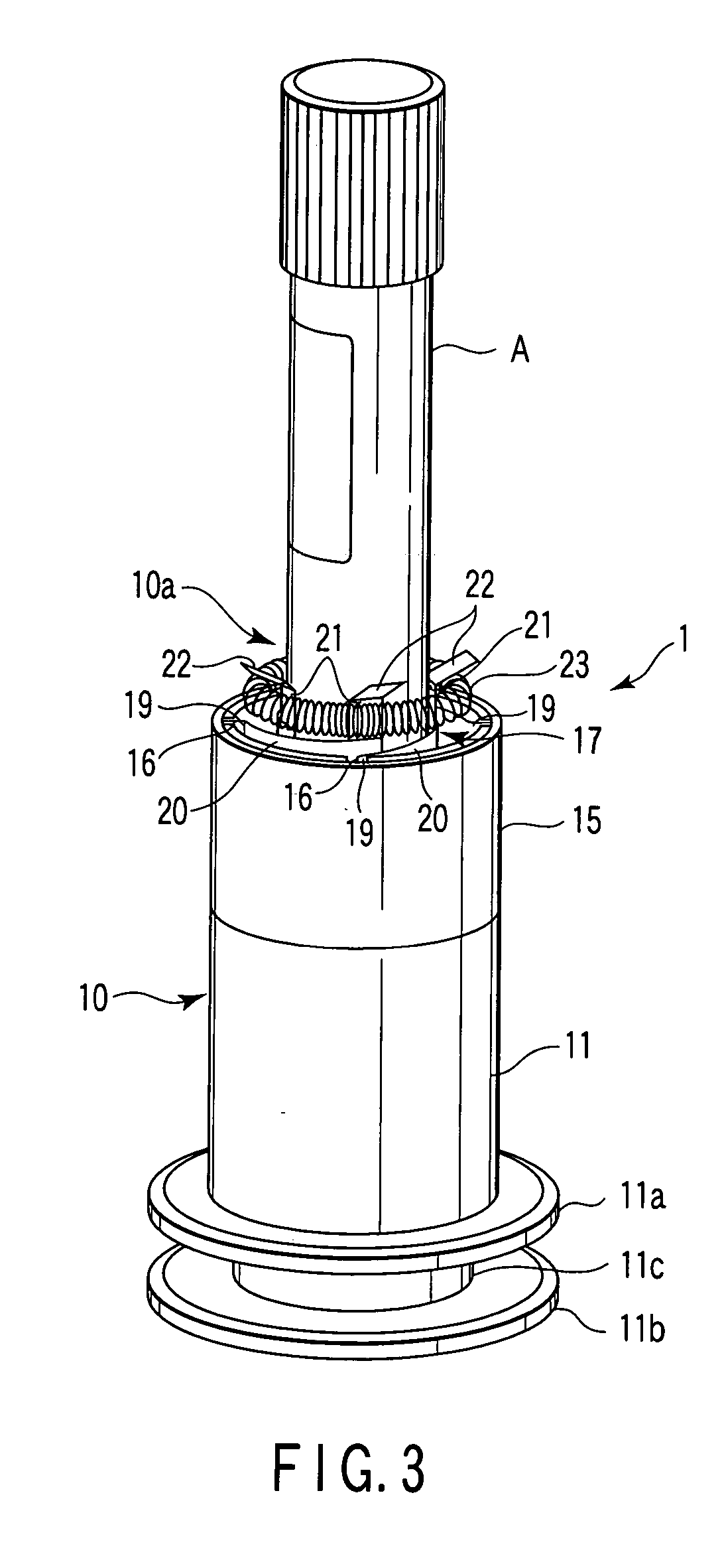
[0019] A test tube holder 1 according to an embodiment of the present invention will be explained in detail hereinafter with reference to FIGS. 1 to 3.

[0020] The test tube holder 1 of the present embodiment comprises a holder main body 10 and a test tube attachment adapter 17. The holder main body 10 is formed of a synthetic resin material. In the holder main body 10, engaging portions that may be engaged with transfer system guide rails (not shown), i.e., flange portions 11a and 11b of two vertical stages in the embodiment, are formed on the outer circumferential surface of the proximal end portion of a cylindrical base body 11, and a ring slot 11c is arranged between the flange portions.

[0021] At the axis center portion of the cylindrical base body 11, a cylindrical hollow portion 12 for inserting a test tube is arranged from the top end portion to a depth equivalent to the position of the flange portion 11a at the upper stage. The outer circumference of the middle area of the c...


PUM

PropertyMeasurementUnit
outer diametersaaaaaaaaaa
transparentaaaaaaaaaa
depthaaaaaaaaaa

Abstract

A test tube holder has a holder main body, which has a cylindrical hollow portion for containing a test tube, and a test tube attachment adapter arranged in the cylindrical hollow portion. The test tube attachment adapter for holding a test tube is configured by plural leaf springs and coil springs and. Each of the leaf springs has a fixed portion, an elastic deformable portion and a test tube holding piece. The fixed portion is fixed to the inner circumference of the cylindrical hollow portion along the axial direction thereof. The elastic deformable portion extends along the circumferential direction from the fixed portion toward the center axis while leaning in the centripetal direction. The test tube holding piece is formed integrally with the elastic deformable portion. The coil springs bundle a top and a bottom end portions of the plural test tube holding pieces.

Description

CROSS-REFERENCE TO RELATED APPLICATIONS [0001] This application is based upon and claims the benefit of priority from prior Japanese Patent Application No. 2004-040022, filed Feb. 17, 2004, the entire contents of which are incorporated herein by reference. BACKGROUND OF THE INVENTION [0002] 1. Field of the Invention [0003] The present invention relates to a test tube holder to be used to transfer a test tube so as to preparatively take or preparatively supply a sample such as blood contained in the test tube. [0004] 2. Description of the Related Art [0005] A test tube in which a sample such as blood is contained is made of transparent glass, and a cap made of rubber or a synthetic resin material is attached to the top opening of the test tube. In order to preparatively take or preparatively supply the sample contained in the test tube, the test tube is transferred to respective processing units in a state in which it is held upright by a test tube holder that is guided along a trans...

Claims


Application Information

Patent Timeline
Patent Type & Authority Applications(United States)
IPC IPC(8): G01N35/04B01L9/00B01L9/06G01N1/00
CPCB01L2200/023B01L9/06E01C11/225E01C2201/202
Inventor ITOH, TERUAKI
Owner IDS CO LTD
Why Eureka
Try Eureka