Irregular shaped copper particles and methods of use

a technology of irregular shape and copper particles, applied in the direction of metal/alloy conductors, conductors, transportation and packaging, etc., can solve the problems of increasing cost, reducing the yield of usable powder, and reducing production costs, so as to improve the conductivity of vehicles, improve the conductivity, and improve the effect of electrical conductivity

Inactive Publication Date: 2005-08-18
SCM METAL PRODUCTS INC
View PDF1 Cites 21 Cited by
  • Summary
  • Abstract
  • Description
  • Claims
  • Application Information

AI Technical Summary

Benefits of technology

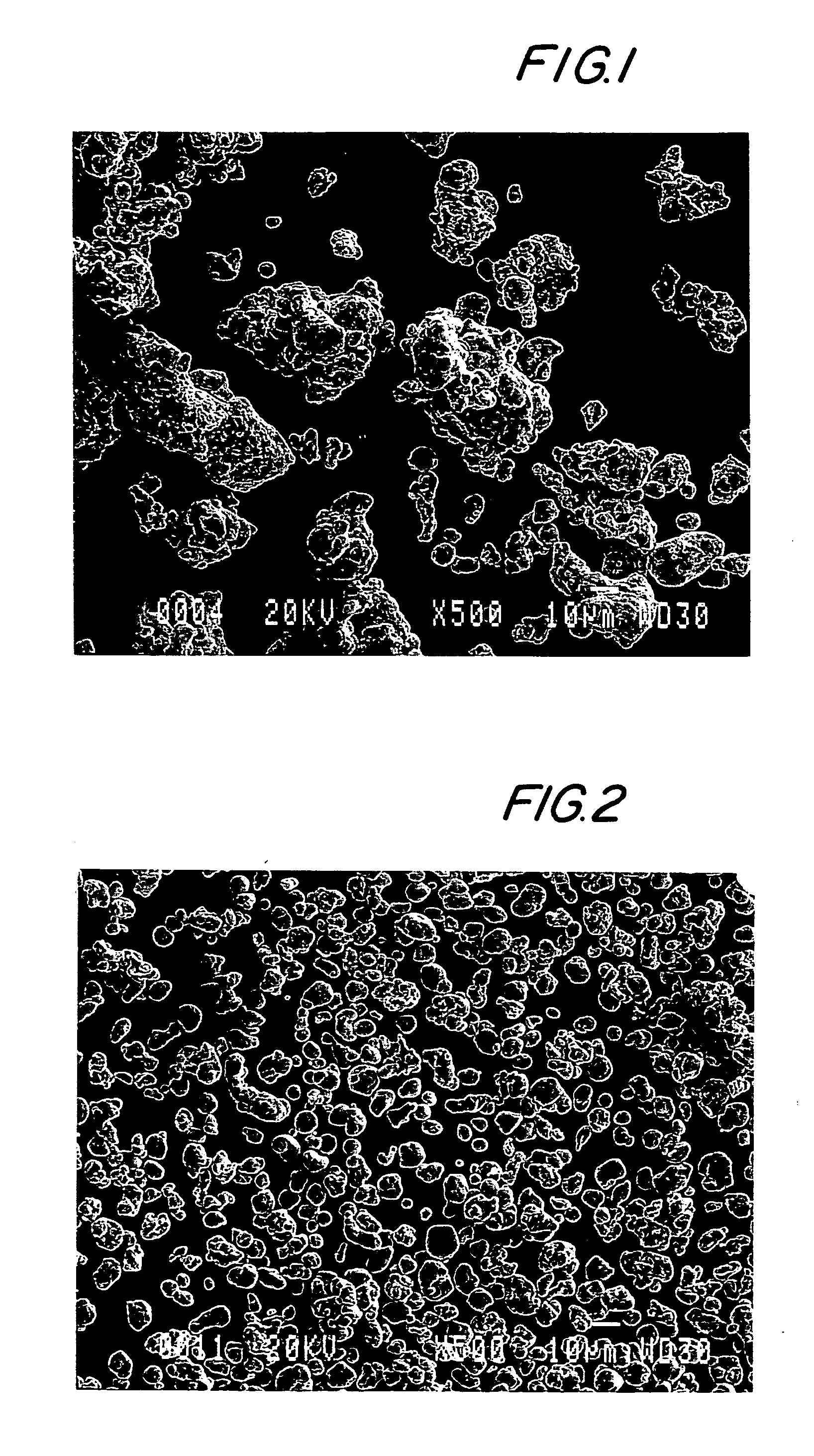
[0011] The present invention provides copper powders with excellent electrical conductivity suitable for microelectronic applications. The copper powders of the present invention are substantially irregular in shape compared to prior art copper powder. This substantially irregular shape provides interlocking electrical contact points between adjacent particles leading to increased conductivity of the vehicle. Moreover, the copper powders of the present invention are oxidatively stable and require no special handling.

Problems solved by technology

There are some disadvantages in using fine copper powders with a D50<10 μm.
One disadvantage is the cost of production.
Selective use of fine particles lowers the yield of usable powder, and thus increases cost as the oversize particles must be either re-melted or scrapped.
Another disadvantage is that copper has tendency to oxidize particularly when it is in fine particle form.
For example, exposing fine copper powder to air for a short period of time will result in surface oxidation.
The oxide form of copper increases contact resistance and reduces electrical conductivity, making it unfit for the some electrical applications i.e. microelectronic adhesives.
However, coating silver on the surface of copper adds significantly to production costs.
One disadvantage associated with copper flakes is that they require special handling to avoid oxidation.

Method used


Image

  • Irregular shaped copper particles and methods of use

Examples


example 1

[0048] High purity electrolytic copper was melted under a reducing atmosphere. The molten copper was poured through a nozzle and the melt stream was broken up by high-pressure water jets. The droplets produced froze instantaneously into powder particles. The powder was dried and screened through a U.S. standard 325 mesh (44 μm) screen. The fraction passing through this screen (<44 μm) was heat treated at 800° F. in hydrogen to reduce any copper oxides present on the surface of the powder particles. The reduced powder was chemically treated to prevent excessive re-oxidation.

Particle Size Distribution

[0049] Table 1 below shows the particle size distribution of the copper particles of the present invention versus particles sizes of silver coated copper powder. It is convenient to show particle size distribution as cumulative percent particles larger than a measured size. For example, D10 value represents 10% particles that are larger than the size shown for the particular powder. D50...

example 2

[0054] 100 parts of a bisphenol-A based epoxy was mixed with 86 parts of anhydride-based hardener to yield an epoxy / hardener system. In this epoxy / hardener system, copper powder prepared in Example 1 was loaded at 78-80% level by weight. The resulting copper containing adhesive was then stencil printed on a FR-4-type board. The adhesive containing board was then cured at 150° C. over a 10-12 minute period. After the adhesive was cured, the volume resistivity was measured using a four-point probe. The volume resistivity of the copper filled adhesive was 10−2 ohm / cm2. This is comparable to the silver-based conductive adhesive used in microelectronic application.


PUM

PropertyMeasurementUnit
D50 particle sizeaaaaaaaaaa
median D50 particle sizeaaaaaaaaaa

Abstract

The present invention provides water atomized copper powder comprising substantially irregular shaped copper particles having at least a median D50 particle size of from about 20 μm or greater to about 50 μm. The powders of the present invention are suitable for use in electrically conductive compositions, such as copper-based adhesives. The present invention also provides methods of making these copper powders.

Description

[0001] This application is a continuation-in-part application of U.S. application Ser. No. 10 / 013,629, filed Dec. 10, 2001 and claims the benefit of the filing date of Provisional Application No. 60 / 256,125, filed Dec. 15, 2000, these entire disclosures are hereby incorporated by reference into the present disclosure.BACKGROUND OF THE INVENTION [0002] Copper powders have been sought for many years for use in electrical applications because of its conductive properties. Copper is also less expensive than other metals (i.e. silver) leading to its wide commercial use. [0003] There has been a considerable research effort to improve the conductivity of copper for microelectronic applications (i.e. adhesives). For this reason, the size of copper powder has been explored for electrical conductivity. In general, copper powder used in conductive adhesives is extremely fine (median particle size D50<10 μm). Fine powder provides more particle contact and consequently higher electrical condu...

Claims


Application Information

Patent Timeline
Patent Type & Authority Applications(United States)
IPC IPC(8): B22F1/052C22C1/04H01B1/02H01B1/22H05K1/09H05K3/32
CPCB22F1/0014B22F2009/0828B22F2998/10C22C1/0425H01B1/026H01B1/22H05K3/321H05K1/095B22F9/082B22F1/0088B22F1/052
Inventor KHATTAR, RAJESHNADKARNI, ANIL V.CHENG, HSIAO L.
Owner SCM METAL PRODUCTS INC
Why Eureka
Try Eureka