LNG system with warm nitrogen rejection

a nitrogen removal and nitrogen technology, applied in lighting and heating equipment, refrigeration machines, solidification, etc., can solve the problems of pipeline availability or capacity exceeding the deliverability of pipelines, pipelines that are not available or are impractical, and achieve the effect of improving the nitrogen removal system

Active Publication Date: 2005-08-25
CONOCOPHILLIPS CO
View PDF15 Cites 47 Cited by
  • Summary
  • Abstract
  • Description
  • Claims
  • Application Information

AI Technical Summary

Benefits of technology

[0010] It is, therefore, an object of the present invention to provide a novel natural gas liquefaction system that employs an enhanced nitrogen removal system that can operate relatively independently of the refrigeration cycles of the natural gas liquefaction system.
[0011] A further object of the invention is to provide a nitrogen removal system which can effectively remove nitrogen from a relatively warm natural gas stream.
[0012] Another object of the invention is to provide an enhanced nitrogen removal system that is less expensive to install and operate than prior systems.

Problems solved by technology

It is desirable to operate the pipeline under a substantially constant and high load factor but often the deliverability or capacity of the pipeline will exceed demand while at other times the demand may exceed the deliverability of the pipeline.
The liquefaction of natural gas is of even greater importance when transporting gas from a supply source which is separated by great distances from the candidate market and a pipeline either is not available or is impractical.
Ship transportation in the gaseous state is generally not practical because appreciable pressurization is required to significantly reduce the specific volume of the gas.
Such pressurization requires the use of more expensive storage containers.
High nitrogen concentrations in natural gas that is subjected to liquefaction in a LNG facility may present one or more of the following drawbacks: (1) the natural gas can be more difficult to condense; (2) the heating value of the natural gas used as fuel gas for the LNG facility's gas turbines can be greatly diminished; and (3) LNG produced by the facility may be out of spec.
The requirement that the feed stream to conventional NRUs be significantly chilled has the disadvantage of increasing the total installed cost of the LNG facility.
However, those skilled in the art recognize that each penetration into and out of a cold box complicates the design of the cold box, thereby adding to its cost.
In addition, the flow lines between the cold box and NRU of a conventional LNG facility require insulation due to the low temperature of the stream flowing therethrough.
Obviously, insulated lines are more expensive to install and maintain than non-insulated lines.

Method used


Image

  • LNG system with warm nitrogen rejection
  • LNG system with warm nitrogen rejection
  • LNG system with warm nitrogen rejection

Examples


Embodiment Construction

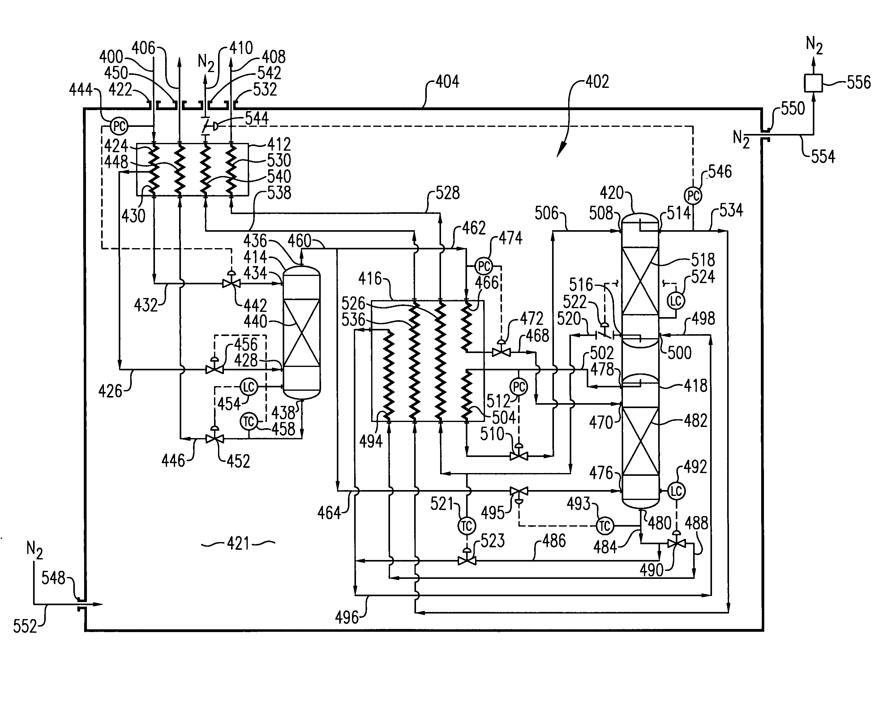
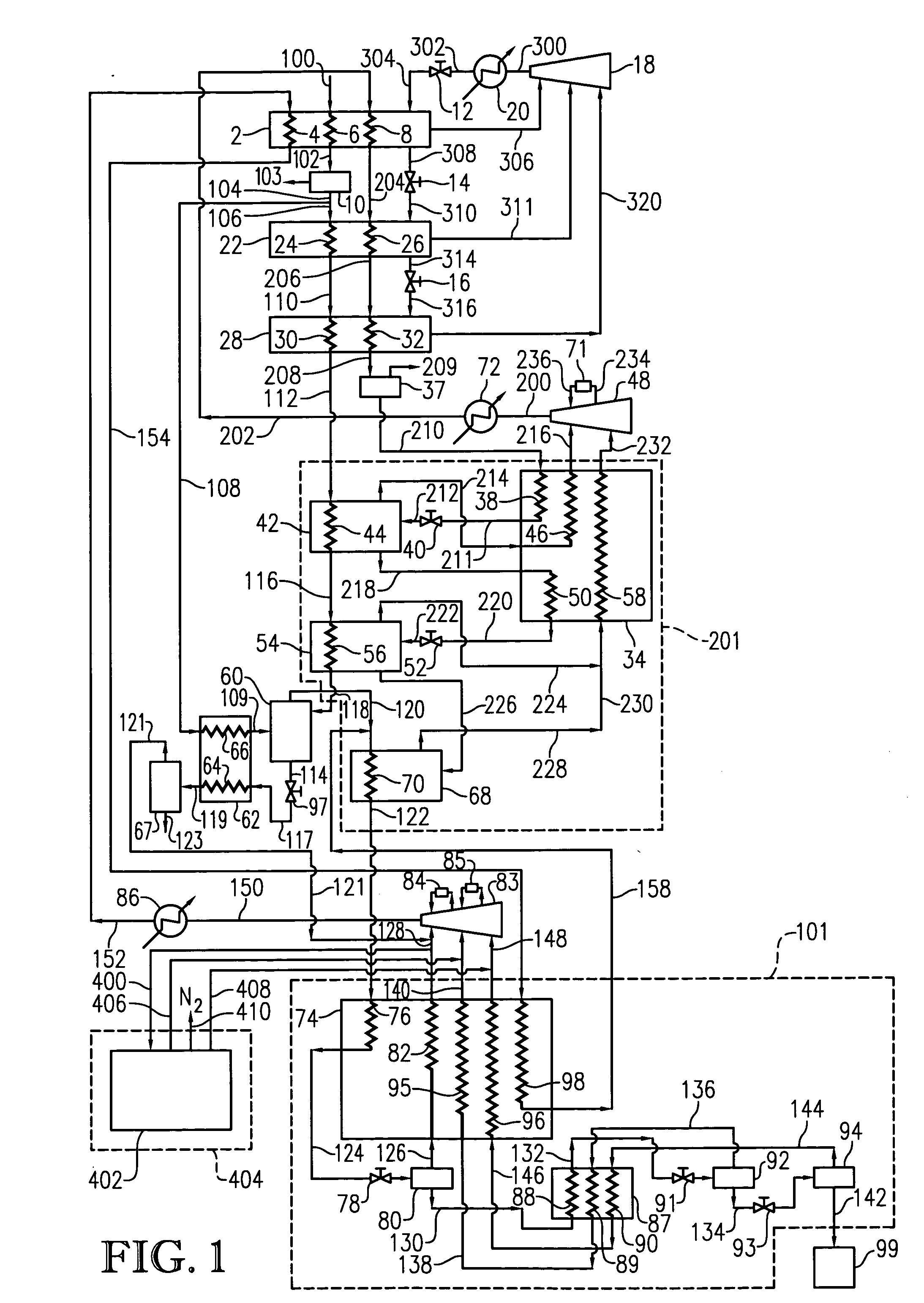
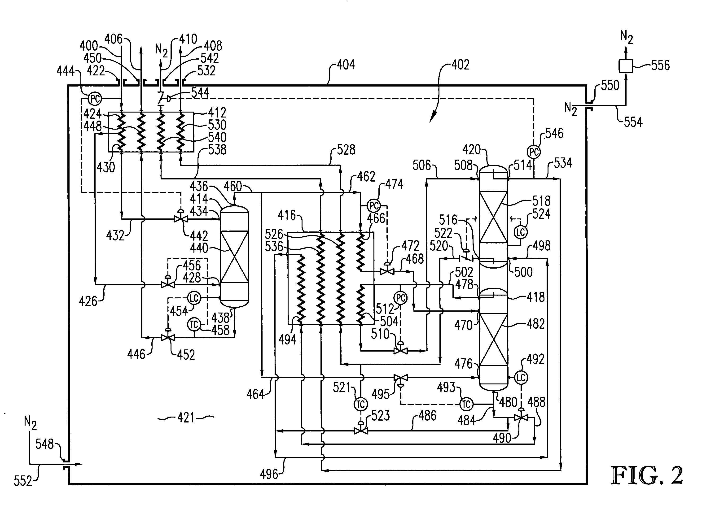
[0024] A cascaded refrigeration process uses one or more refrigerants for transferring heat energy from the natural gas stream to the refrigerant and ultimately transferring said heat energy to the environment. In essence, the overall refrigeration system functions as a heat pump by removing heat energy from the natural gas stream as the stream is progressively cooled to lower and lower temperatures. The design of a cascaded refrigeration process involves a balancing of thermodynamic efficiencies and capital costs. In heat transfer processes, thermodynamic irreversibilities are reduced as the temperature gradients between heating and cooling fluids become smaller, but obtaining such small temperature gradients generally requires significant increases in the amount of heat transfer area, major modifications to various process equipment, and the proper selection of flow rates through such equipment so as to ensure that both flow rates and approach and outlet temperatures are compatibl...


PUM


Abstract

Natural gas liquefaction system employing an enhanced nitrogen removal system capable of removing nitrogen from a relatively warm natural gas stream.

Description

BACKGROUND OF THE INVENTION [0001] 1. Field of the Invention [0002] This invention relates to a method and apparatus for liquefying natural gas. In another aspect, the invention concerns an improved liquified natural gas (LNG) facility employing an enhanced nitrogen removal system. In still another aspect, the invention relates to a method and apparatus for removing nitrogen from a relatively warm natural gas stream. [0003] 2. Description of the Prior Art [0004] The cryogenic liquefaction of natural gas is routinely practiced as a means of converting natural gas into a more convenient form for transportation and storage. Such liquefaction reduces the volume of the natural gas by about 600-fold and results in a product which can be stored and transported at near atmospheric pressure. [0005] Natural gas is frequently transported by pipeline from the supply source to a distant market. It is desirable to operate the pipeline under a substantially constant and high load factor but often ...

Claims


Application Information

Patent Timeline
Patent Type & Authority Applications(United States)
IPC IPC(8): F25J1/02F25J3/02
CPCF25J3/0209F25J3/0295F25J3/0257F25J2200/08F25J2200/70F25J2210/06F25J2220/62F25J2220/64F25J2245/02F25J2270/12F25J2280/02F25J2290/30F25J2290/42F25J1/0022F25J1/004F25J1/0052F25J1/021F25J1/0265F25J2215/04F25J2270/60Y10S62/927F25J1/0261F25J3/0233
Inventor HAHN, PAUL R.RITCHIE, PHILLIP D.YAO, JAMELEE, RONG-JWYNEATON, ANTHONY P.LOW, WILLIAM R.
Owner CONOCOPHILLIPS CO
Why Eureka
Try Eureka