Tuning electrodes used in a reactor for electrochemically processing a microelectric workpiece

a micro-electric workpiece and electrode technology, applied in the direction of electrolysis components, vacuum evaporation coatings, coatings, etc., can solve the problems of manual trial and error, affecting the uniformity of the desired process, and the inability to determine the electrical parameters of each electrode in the array to achieve the desired process uniformity, etc., to achieve the effect of reducing labor costs, high uniformity, and increasing output quality and throughpu

Inactive Publication Date: 2005-08-25
WILSON GREGORY J +3
View PDF99 Cites 23 Cited by
  • Summary
  • Abstract
  • Description
  • Claims
  • Application Information

AI Technical Summary

Benefits of technology

[0016] In the following, a facility for automatically identifying electrical parameters that produce a high level of uniformity in electrochemically processing a microelectronic workpiece is described. Embodiments of this facility are adapted to accommodate various electrochemical processes; reactor designs and conditions; plating materials and solutions; workpiece dimensions, materials, and conditions, and the nature and condition of existing coatings on the workp...

Problems solved by technology

As the size of various microelectronic circuits and components decreases, there is a corresponding decrease in the manufacturing tolerances that must be met by the manufacturing tools.
However, determining the electrical parameters for each of the electrodes in the array to achieve the desired process uniformity can be problematic.
Using such a manual trial and error approach, however, can be very time-consuming.
Further, the electrical parameters do not easily translate to other electrochemical processes.
For example, a given set of electrical parameters used to electroplate a metal to a thickness X onto the surface of a microelectronic workpiece cannot easily be used to derive the electrical parameters used to electroplate a metal to a thickness Y. Still further, the electr...

Method used


Image

  • Tuning electrodes used in a reactor for electrochemically processing a microelectric workpiece
  • Tuning electrodes used in a reactor for electrochemically processing a microelectric workpiece
  • Tuning electrodes used in a reactor for electrochemically processing a microelectric workpiece

Examples


Embodiment Construction

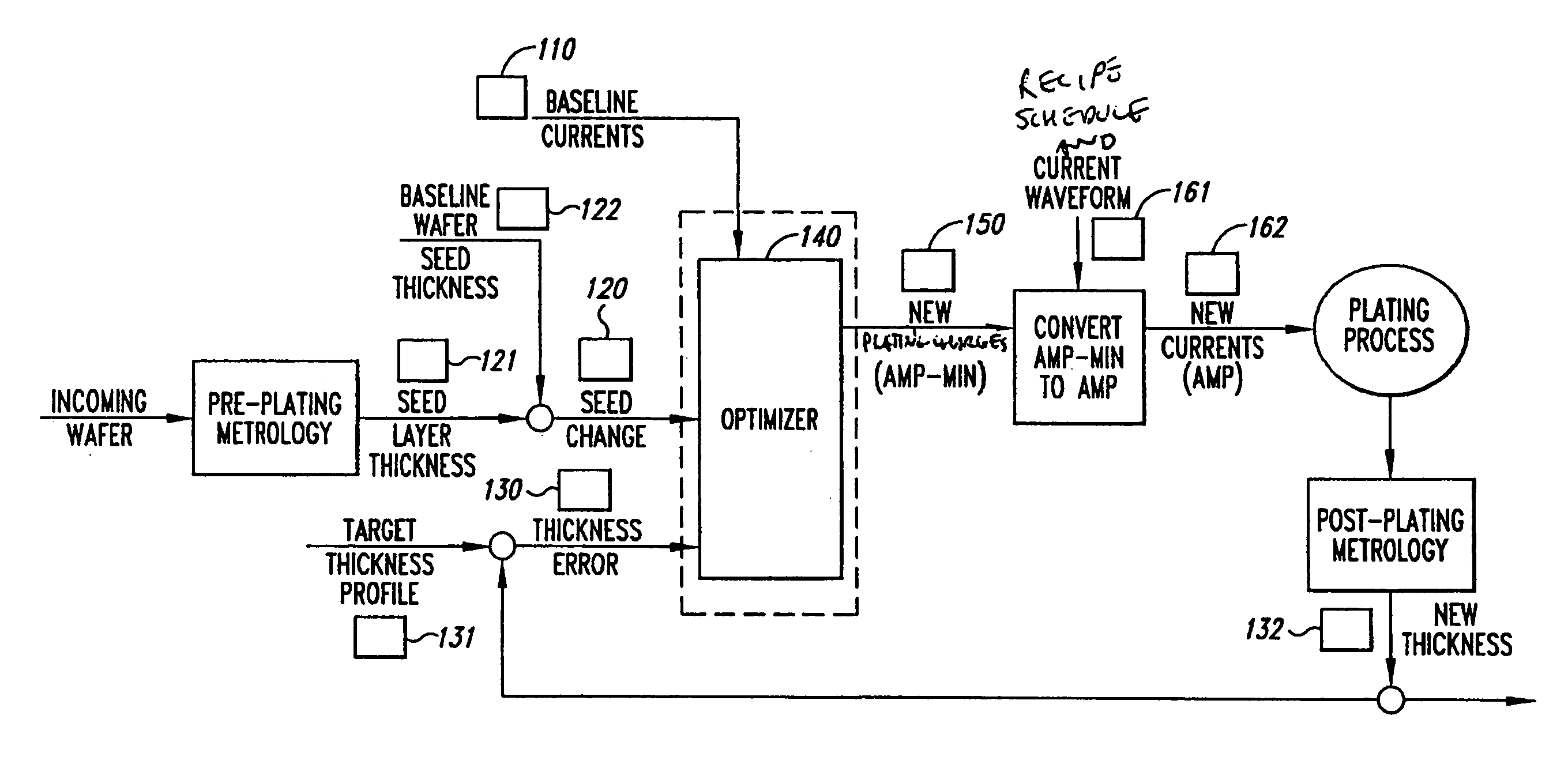
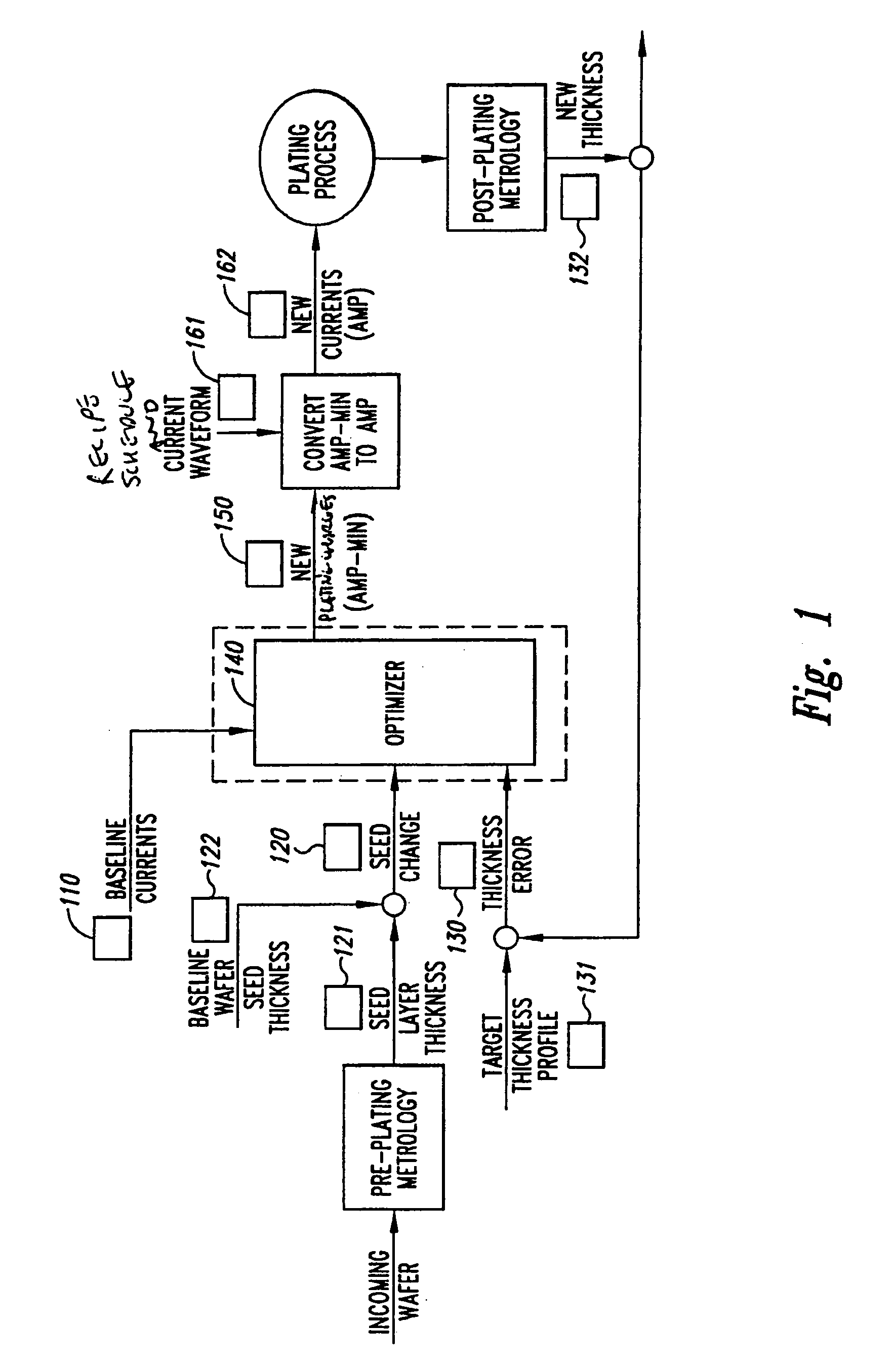
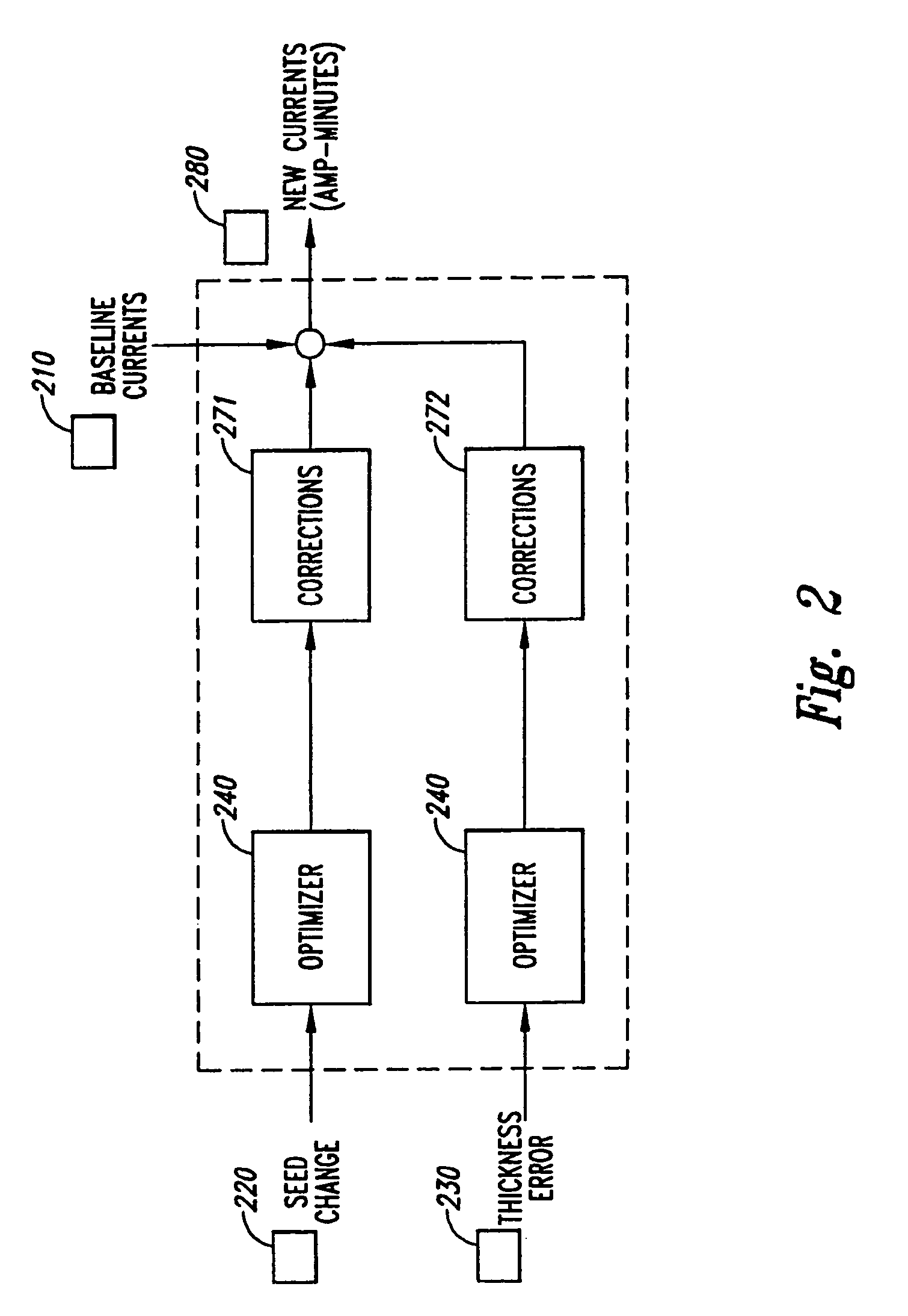
[0033] A facility for automatically selecting and refining electrical parameters for processing a microelectronic workpiece (“the optimizer”) is disclosed. In many embodiments, the optimizer determines process parameters affecting the processing of a round workpiece as a function of processing results at various radii on the workpiece. In some embodiments, the optimizer adjusts the electrode currents for a multiple electrode electroplating chamber, such as multiple anode reaction chambers of the Paragon tool provided by Semitool, Inc. of Kalispell, Mont., in order to achieve a specified thickness profile (i.e., flat, convex, concave, etc.) of a coating, such as a metal or other conductor, applied to a semiconductor wafer. The optimizer adjusts electrode currents for successive workpieces to compensate for changes in the thickness of the seed layer of the incoming workpiece (a source of feed forward control), and / or to correct for non-uniformities produced in prior wafers at the anod...


PUM

PropertyMeasurementUnit
Fractionaaaaaaaaaa
Fractionaaaaaaaaaa
Fractionaaaaaaaaaa

Abstract

A facility for selecting and refining electrical parameters for processing a microelectronic workpiece in a processing chamber is described. The facility initially configures the electrical parameters in accordance with either a mathematical model of the processing chamber or experimental data derived from operating the actual processing chamber. After a workpiece is processed with the initial parameter configuration, the results are measured and a sensitivity matrix based upon the mathematical model of the processing chamber is used to select new parameters that correct for any deficiencies measured in the processing of the first workpiece. These parameters are then used in processing a second workpiece, which may be similarly measured, and the results used to further refine the parameters. In some embodiments, the facility analyzes a profile of the seed layer applied to a workpiece, and determines and communicates to a material deposition tool a set of control parameters designed to deposit material on the workpiece in a manner that compensates for deficiencies in the seed layer.

Description

CROSS-REFERENCES TO RELATED APPLICATIONS [0001] The present application is a continuation-in-part of U.S. patent application Ser. No. 09 / 849,505, filed May 4, 2001, which claims the benefit of U.S. Provisional Patent Application No. 60 / 206,663, filed May 24, 2000, and which is a continuation-in-part of International Patent Application No. PCT / US00 / 10120, filed Apr. 13, 2000, designating the United States and claiming the benefit of U.S. Provisional Patent Application No. 60 / 182,160, filed Feb. 14, 2000, No. 60 / 143,769, filed Jul. 12, 1999, and No. 60 / 129,055, filed Apr. 13, 1999; and this application claims the benefit of provisional application No. 60 / 206,663, filed May 24, 2000; the disclosures of each of which are hereby expressly incorporated by reference in their entireties. FIELD OF THE INVENTION [0002] The present invention is directed to the field of automatic process control, and, more particularly, to the field of controlling a material deposition process.BACKGROUND OF THE...

Claims


Application Information

Patent Timeline
IPC IPC(8): C23C14/54C23C16/52C25D7/12C25D21/12
CPCC23C14/545C25D7/123C25D21/12C23C16/52
Inventor WILSON, GREGORY J.MCHUGH, PAUL R.WEAVER, ROBERT A.RITZDORF, THOMAS L.
Owner WILSON GREGORY J
Why Eureka
Try Eureka