Modular anti-icing/de-icing device for an aerodynamic surface

Inactive Publication Date: 2005-08-25
EUROCOPTER
View PDF29 Cites 63 Cited by
  • Summary
  • Abstract
  • Description
  • Claims
  • Application Information

AI Technical Summary

Benefits of technology

[0007] An object of the present invention-is to propose an active anti-icing/de-icing device that is effective regardless of the

Problems solved by technology

Consequently, the connections between the modules and the power switch unit comprise a large number of cables, which is extremely penalizing in terms of weight.
Nevertheless, because of variations in the flow of air over the aerodynamic surface, because of the possib

Method used


Image

  • Modular anti-icing/de-icing device for an aerodynamic surface
  • Modular anti-icing/de-icing device for an aerodynamic surface
  • Modular anti-icing/de-icing device for an aerodynamic surface

Examples


first embodiment

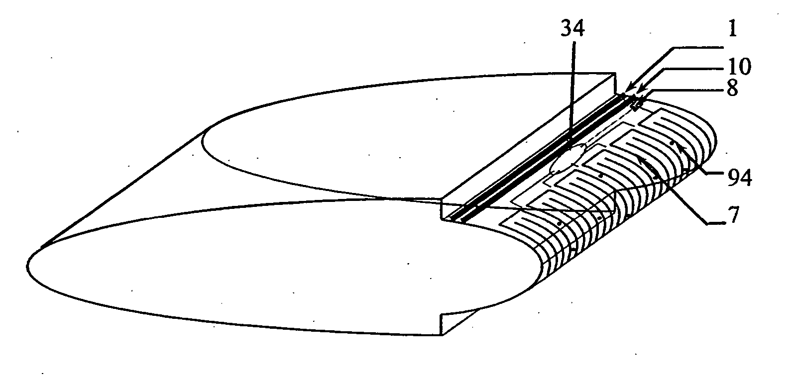
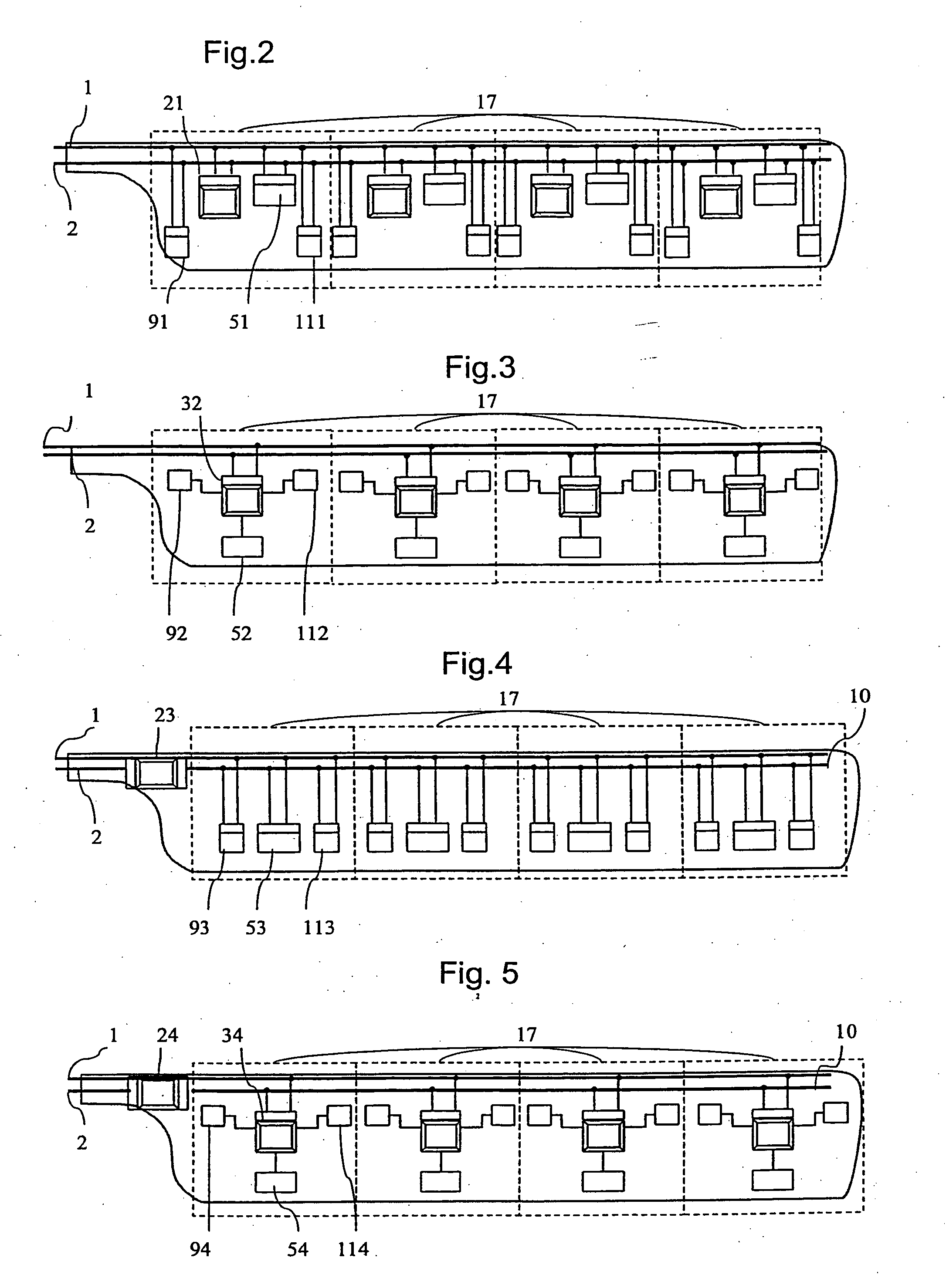
[0045]FIG. 2 shows a Each module 17 is fitted with a first regulator unit 21, e.g. a peripheral microprocessor. This first regulator unit 21 receives a first measurement signal from a temperature sensor 91 and a first monitoring signal from an ice sensor 111 in order to control a first heater element 51. All of these components are provided with respective CAN interfaces and they are connected to the main communications means 2.

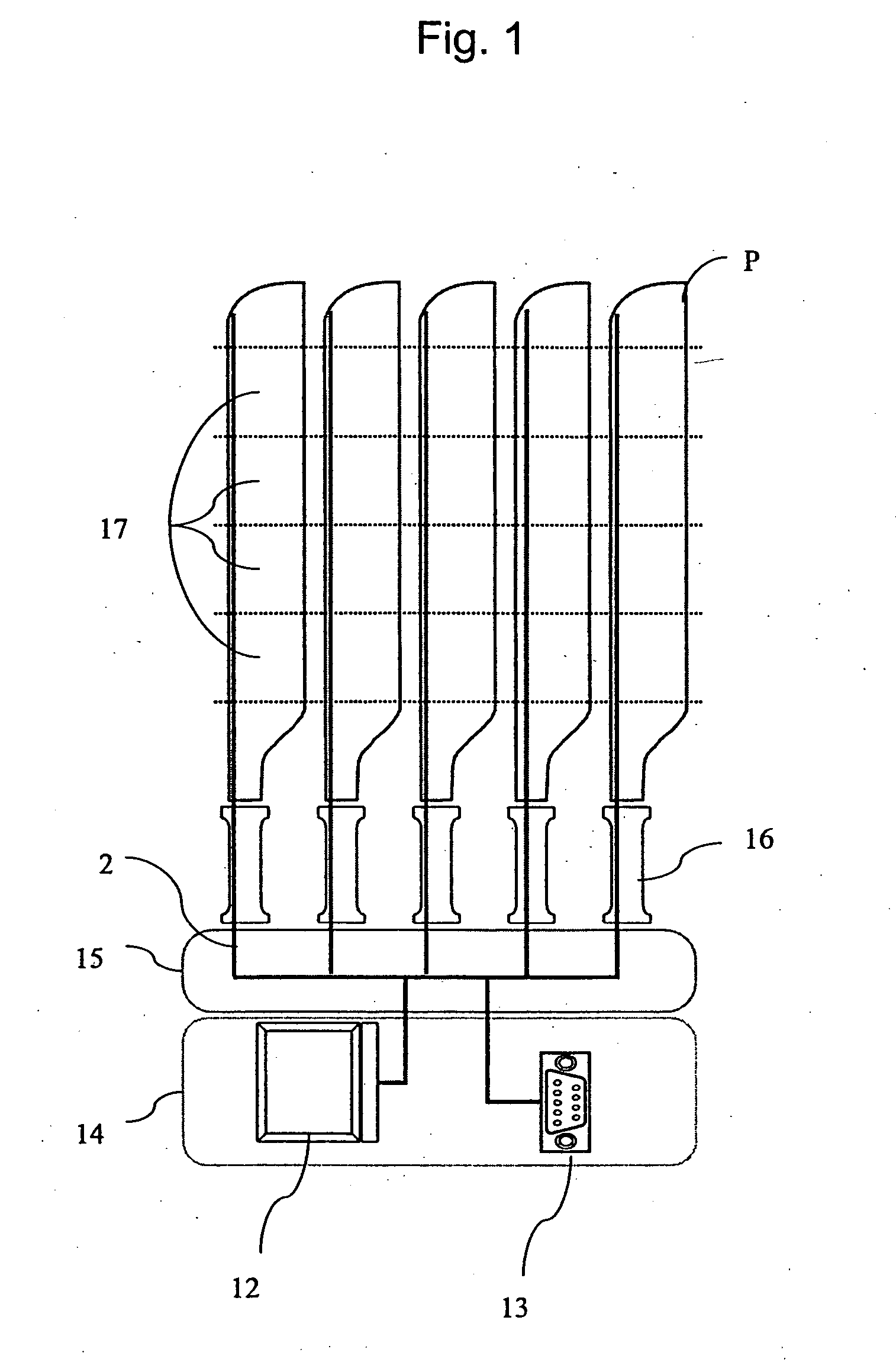
[0046] The system relies on the single main communications means 2 which makes it much easier to implement. In addition, all of the modules 17 in a given blade are powered by a single electrical power supply means 1, e.g. an electrical power supply cable.

second embodiment

[0047]FIG. 3 shows a Each module 17 is provided with a second regulator unit 32, e.g. a microcontroller, connected to the main communications bus 2 and provided with a CAN interface. This second regulator unit 32 receives a second measurement signal from a temperature sensor 92 and a second monitoring signal from an ice sensor 112 in order to control a second heater element 52.

[0048] In addition, by implementing a microcontroller, it is possible to achieve better integration of the peripheral elements (temperature sensors, ice sensors, and heater elements). Each of these peripheral elements is identifiable by its predefined connection to one of the pins of the microcontroller. The anti-icing / de-icing modules are completely independent. The microcontroller dialogs via the main communications means 2 with the central microprocessor 12 or the diagnosis connector 13, thereby facilitating tests and maintenance operations.

[0049] This second embodiment considerably reduces the number of ...

third embodiment

[0050]FIG. 4 shows a In this case, a third regulator unit communicates with all of the modules 17 of the blade. This third regulator unit 23 provided with two CAN interfaces, an auxiliary microprocessor for example, is disposed at the root of the blade. The two CAN interfaces enable a gateway to be established between the main communications means 2 and a secondary communications means 10 which is advantageously a bus using a both-way protocol. Consequently, the third regulator unit 23 is connected to the central microprocessor 12 via the main communications means 0.2, and also to the various anti-icing / de-icing modules 17 of the blade via the secondary communications means 10 specific to the blade.

[0051] Each module 17 is provided with a temperature sensor 93, an ice sensor 113, and a heater element 53, with each of these components being provided with a respective CAN interface enabling it to be connected to the secondary communications bus 10. These temperature sensors 113 and i...


PUM


Abstract

A anti-icing/de-icing device for an aircraft wing includes at least one aerodynamic surface, e.g. a rotorcraft blade or an airplane wing, the aerodynamic surface possessing at least two anti-icing/de-icing modules 17, with each module 17 being provided with a respective heater element 54. In addition, the heater elements 54 of the modules 17 are powered electrically by a common electrical power supply member 1, each anti-icing/de-icing module acting against icing in its own zone independently of the other module(s).

Description

[0001] The present invention relates to a modular anti-icing / de-icing device for an aerodynamic surface. More particularly, the aerodynamic surfaces concerned are those having an aerodynamic profile that must not be disturbed by the formation of ice. Such aerodynamic surfaces correspond in particular to the blades of a rotorcraft (main rotor and antitorque rotor) or indeed the wings of an airplane. BACKGROUND OF THE INVENTION [0002] The problem of such aerodynamic surface icing is well known in the aviation industry. The aerodynamic profile of such a surface can become modified by ice forming thereon, as a result of the flying aerodynamic surface encountering droplets of super-cooled water contained in the atmosphere. [0003] This problem is often treated by fitting the aerodynamic surface with a heater structure. [0004] To do this, e.g. in a rotorcraft, a plurality of heater resistances are embedded in the blades of the main rotor and of the tail rotor. In order to reduce significan...

Claims


Application Information

Patent Timeline
IPC IPC(8): B64D15/12B64D15/22
CPCB64C27/04B64D15/22B64D15/12
Inventor BOURJAC, DIDIERCUADRADO, GERARD
Owner EUROCOPTER
Why Eureka
Try Eureka