Method of manufacture of a chromogenic panel

Inactive Publication Date: 2005-08-25
MARTINO JOHN
View PDF7 Cites 6 Cited by
  • Summary
  • Abstract
  • Description
  • Claims
  • Application Information

AI Technical Summary

Benefits of technology

[0009] The invention is a method of manufacturing a chromogenic panel including the steps of securing at least one chromogenic matrix layer between a first electrically conductive surface of a first substrate and a second electrically conductive surface of a second substrate to form a chromogenic film. Next, a partial vacuum is applied through a plurality of throughbores defined within a flat cutting surface to secure the chromogenic film to the flat cutting surface. A laser beam is applied to cut a perime

Problems solved by technology

The laser beam is applied using only enough energy to cut through the substrates and their adjacent conductive surfaces but not

Method used


Image

  • Method of manufacture of a chromogenic panel
  • Method of manufacture of a chromogenic panel
  • Method of manufacture of a chromogenic panel

Examples


Embodiment Construction

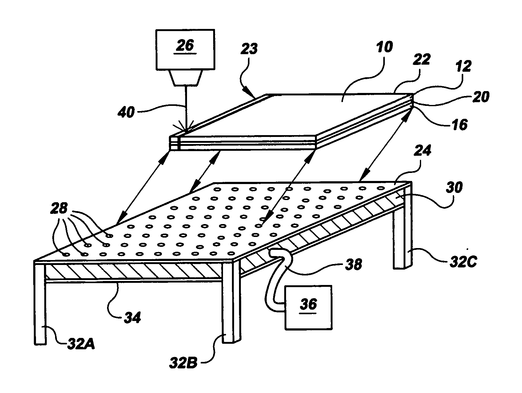
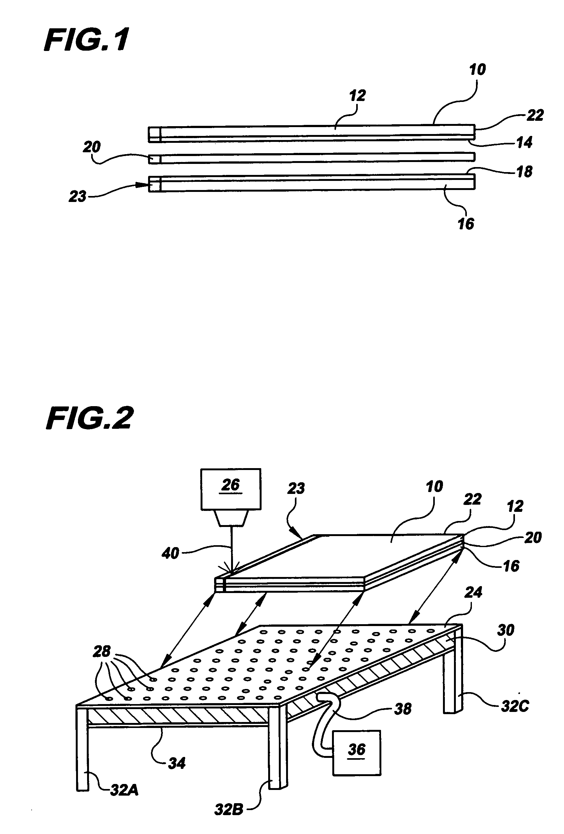
[0023] The invention is a method of manufacturing a chromogenic panel 10 that provides for varying optical characteristics in response to varying energy signals. The method comprises the steps of first securing at least one chromogenic matrix 20 between a first electrically conductive surface 14 of a first substrate 12 and a second electrically conductive 16 surface of a second substrate 18 to form a chromogenic film 23 as best shown in FIG. 1. Next, the chromogenic film 23 is secured to an especially flat cutting surface 24. It has been determined by the inventors herein that use of a laser 26 to cut the chromogenic panel 10 requires that the surface of the panel 10 being cut must be extremely flat. Therefore, a flat cutting surface 24 for purposes herein is defined to have no variations within a plane of the surface 24 that are greater than plus or minus one-fiftieth of an inch, or preferably, plus or minus one-hundredth of an inch.

[0024] The flat cutting surface 24 of the presen...


PUM


Abstract

An improved method of manufacture of a chromogenic panel (10) includes the steps of securing a chromogenic matrix (20) between conductive surfaces (14, 18) of first and second substrates (12, 16) to form a chromogenic film (23); applying a partial vacuum through a plurality of throughbores (28) in a flat cutting surface (24) to secure the film (23) to the cutting surface (24); and using a laser beam (40) to cut a perimeter edge (22), bus-bar cut-outs (54, 62), or an image field line (75) within the substrates (12, 16) to form and manufacture the chromogenic panel (10). The partial vacuum applied through the flat cutting surface (24) provides for an exceptionally flat cutting surface of the panel (10) to facilitate precise focus and cutting by the laser beam (40).

Description

CROSS REFERENCE TO RELATED APPLICATION [0001] This Application claims the benefit of U.S. Provisional Patent Application Ser. No. 60 / 546,496 that was filed on Feb. 20, 2004, entitled “Method of Manufacture of a Chromogenic Panel”.TECHNICAL FIELD [0002] The present invention relates to chromogenic panels that provide varying optical properties in response to varying electrical signals, and especially relates to an improved method of manufacture of a chromogenic panel. BACKGROUND ART [0003] Chromogenic panels are well known for providing varying optical properties in response to varying electrical or other signals, as disclosed for example in U.S. Pat. No. 6,039,390 that issued on Mar. 21, 2000 for a “Chromogenic Window Assembly Construction and Other Chromogenic Devices”. As shown in FIG. 1, a typical chromogenic panel generally designated by the reference numeral 10 includes a first substrate 12 having a first electrically conductive surface 14, a second substrate 16 having a second...

Claims


Application Information

Patent Timeline
IPC IPC(8): B60J7/00B60R13/07B62D25/06B62D25/07G02F1/1333G02F1/1341G02F1/161
CPCG02F1/161G02F1/1341G02F1/133305
Inventor MARTINO, JOHN
Owner MARTINO JOHN
Why Eureka
Try Eureka