Distortion compensation circuit, power amplifier using distortion compensation circuit, and distortion compensation signal generating method

a distortion compensation circuit and power amplifier technology, applied in the direction of distortion compensation circuits, multiplex communication, amplifier modifications to reduce non-linear distortion, etc., can solve the problems of not being able to recognize the sizes of amplitude and phase distortion, not being able to recognize the amounts of third, fifth and seventh-order phase distortion components respectively contained in amplitude distortion, and not being able to accurately and quickly generate distortion compensation signals. , to achieve the effect of improving the accuracy of distortion compensation,

Inactive Publication Date: 2005-08-25
KOKUSA ELECTRIC CO LTD
View PDF4 Cites 18 Cited by
  • Summary
  • Abstract
  • Description
  • Claims
  • Application Information

AI Technical Summary

Benefits of technology

[0019] It is an object of the present invention to provide a distortion compensating circuit which, for use when making distortion compensation for a power amplifier, improves the accuracy of distortion compensation and increases the speed of distortion convergence by accurately and quickly generating distortion compensating signals and which adjusts the distortion components, generated in the power amplifier, to be reduced according to the characteristics of the power amplifier.
[0020] It is another object of the present invention to provide a distortion compensating circuit that makes distortion compensation for a lower amplitude level of the input signal.

Problems solved by technology

In this method, however, it is not possible to recognize the sizes of amplitude and phase distortions.
In addition, it is not possible to recognize what amounts of the third, fifth and seventh-order amplitude distortion components are respectively contained in the amplitude distortion.
Likewise it is not possible to recognize what amounts of the third, fifth and seventh-order phase distortion components are respectively contained in the phase distortion.
Accordingly, it is clear that in this method, the accuracy of compensation is low and the compensating speed (convergence) is remarkably large.
Because only the difference is calculated in the technique described in aforementioned Document 2, the error in the difference value cannot be ignored if the amplitude of the input signal is small and therefore distortion compensation cannot be performed.
In addition, although the frequency characteristics of the output signal should preferably be linear with respect to those of the input signal of the power amplifier, it is difficult to make them uniformly linear due to the variation in the characteristics of semiconductor devices constituting the power amplifier.

Method used


Image

  • Distortion compensation circuit, power amplifier using distortion compensation circuit, and distortion compensation signal generating method
  • Distortion compensation circuit, power amplifier using distortion compensation circuit, and distortion compensation signal generating method
  • Distortion compensation circuit, power amplifier using distortion compensation circuit, and distortion compensation signal generating method

Examples


Embodiment Construction

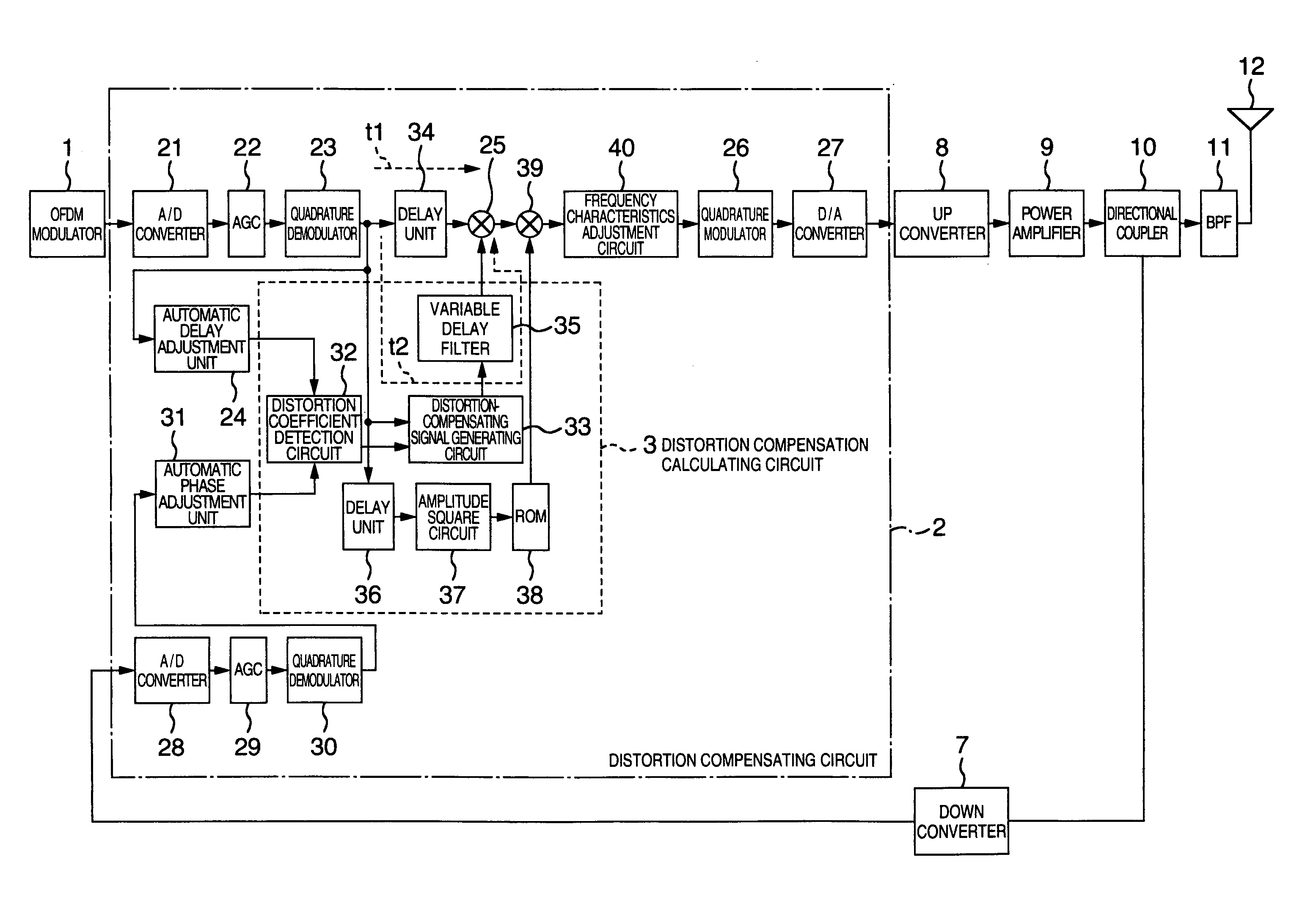
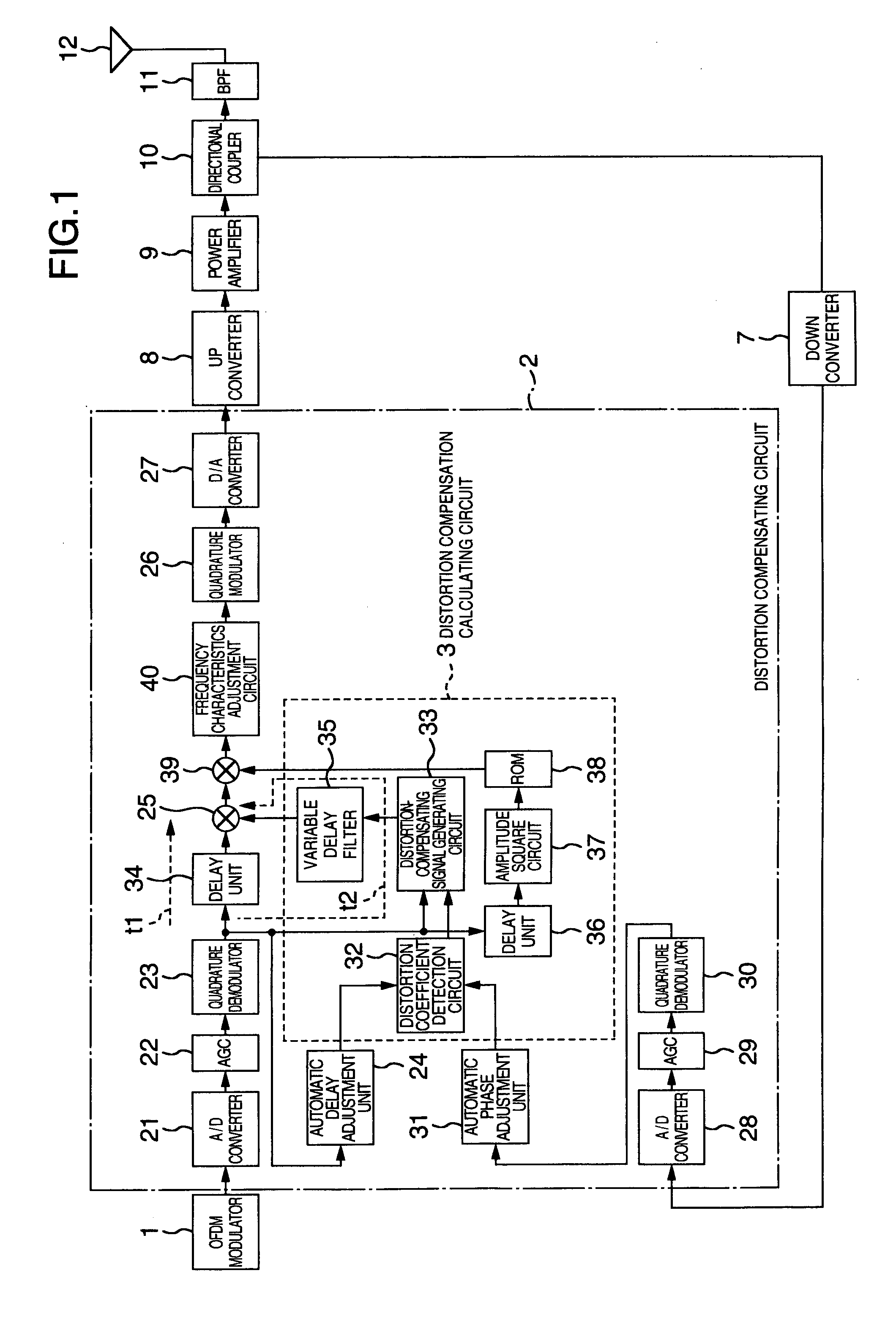
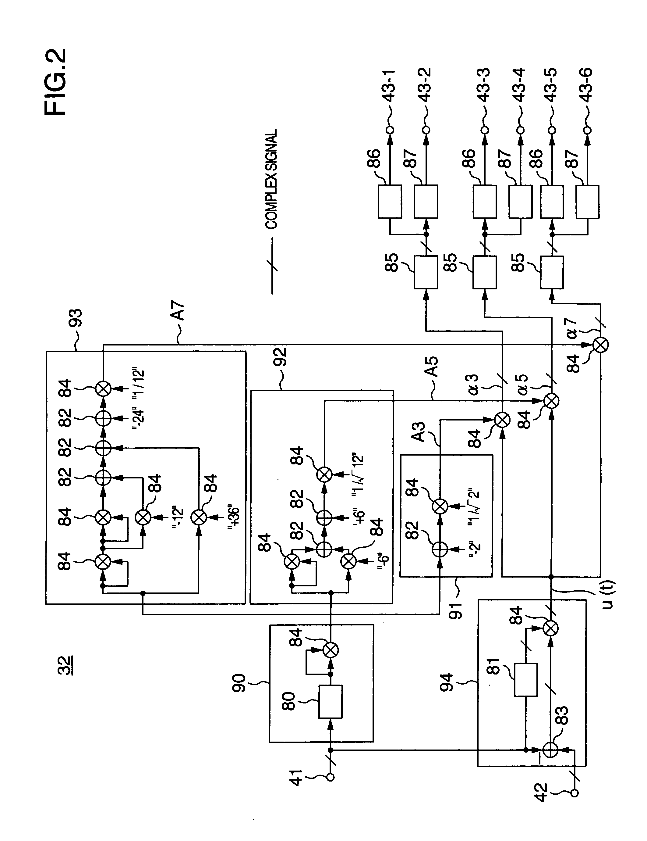
[0048] The following describes an embodiment of the present invention.

[0049] In the embodiment of the present invention, two types of compensating signals according to respective input signal levels are generated for use as distortion compensating signals. One compensating signal is an autonomous correction-compensating signal for relatively large amplitude levels of the input signal. The other compensating signal is a fixed correction-compensating signal for relatively small levels of the input signal.

[0050] The autonomous correction-compensating signal is described below.

[0051] Firstly, a description will be made of the theory to determine the distortion introduced by a power amplifier so as to generate the distortion-compensating signal that counteracts the characteristic of the power amplifier. Generally, the power amplifying circuit is characterized by the following expanded equation (1) expressed with input signal Vin and output signal Vout: Vout=α0+α1·Vin+α2·Vin2+α⁢ ⁢3·Vi...


PUM


Abstract

A distortion compensating circuit for a power amplifier attains raised compensating accuracy with shorter convergence time by accurately and quickly generating a distortion compensation signal for predistortion. An error signal representing the difference between the input and output signals of the power amplifier is generated. From the error signal and the input signal, the coefficients of the third-order intermodulation distortion, fifth-order intermodulation distortion and seventh-order intermodulation distortion are calculated. According to these coefficients, a distortion compensating signal which is characteristically opposite in phase and gain to the intermodulation distortions is generated.

Description

CROSS-REFERENCE TO RELATED APPLICATION [0001] The present invention is related to WO 2004 / 045067 published on May 27, 2004 entitled “DISTORTION COMPENSATION CIRCUIT, DISTORTION COMPENSATION SIGNAL GENERATING METHOD, AND POWER AMPLIFIER”, the entire content of which is incorporated herein by reference for all purposes. INCORPORATION BY REFERENCE [0002] The present application claims priority from Japanese application JP 2004-049442 filed on Feb. 25, 2004, the content of which is hereby incorporated by reference into this application. BACKGROUND OF THE INVENTION [0003] The present invention relates to a non-linear distortion compensating technique for reducing non-linear distortion components output from a transmitter that transmits radio waves amplified in power by a power amplifier. [0004] An example of a conventional non-linear distortion compensating technique, in particular, a predistorting compensation method, is described in Eijogakugiho Vol. 24, No. 79, BCS2000-92 “An Adaptive...

Claims


Application Information

Patent Timeline
Patent Type & Authority Applications(United States)
IPC IPC(8): H03F1/26H03F1/32H03F3/24H04B1/04H04J11/00
CPCH03F1/3258H03F1/3247
Inventor HIROSE, NOBUOMURATA, NOBUOTADA, YASUTOSHITSUKAMOTO, NOBUO
Owner KOKUSA ELECTRIC CO LTD
Why Eureka
Try Eureka