Object lens driving device, optical pickup, and optical disk drive

a driving device and optical pickup technology, applied in the direction of data recording, instruments, disposition/mounting of heads, etc., can solve the problems of easy chromatic aberration, degraded light spot quality, recording and reproduction quality may decline, etc., and achieve superior tilt characteristics

Inactive Publication Date: 2005-08-25
RICOH KK
View PDF64 Cites 32 Cited by
  • Summary
  • Abstract
  • Description
  • Claims
  • Application Information

AI Technical Summary

Benefits of technology

[0039] A specific object of the present invention is to provide an object lens driving device able to reduce tilts arising in a supporting system therein during focusing and tracking operations, and an optical pickup and an optical disk drive.
[0063] According to the above invention, by using an object lens driving device superior in tilt characteristics, it is possible to provide an optical disk drive able to read and write data under good conditions.

Problems solved by technology

When the NA of the object lens is increased or the wavelength of the incident laser light is decreased, however, the optical axis of the object lens turns out to deviate from the normal direction of the recording medium, and this may induce chromatic aberration easily.
Due to this, the quality of the light spot may degrade, and the recording and reproduction quality may decline.
However, even for such an object lens driving device capable of tilt driving, if the tilts arising in focusing and tracking operations are large, servo-control in the device is liable to be out of phase.
On the other hand, when performing focusing and tracking at the same time, there arises a problem in that radial tilt (rotation) may take place.

Method used


Image

  • Object lens driving device, optical pickup, and optical disk drive
  • Object lens driving device, optical pickup, and optical disk drive
  • Object lens driving device, optical pickup, and optical disk drive

Examples


first embodiment

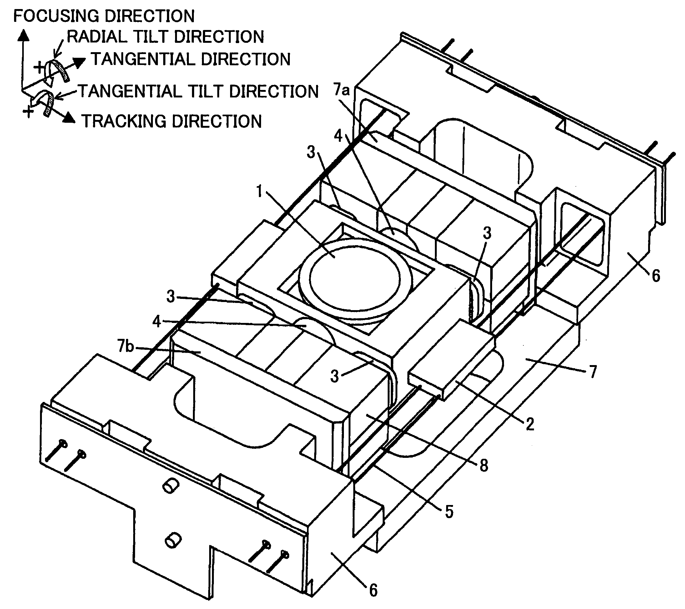
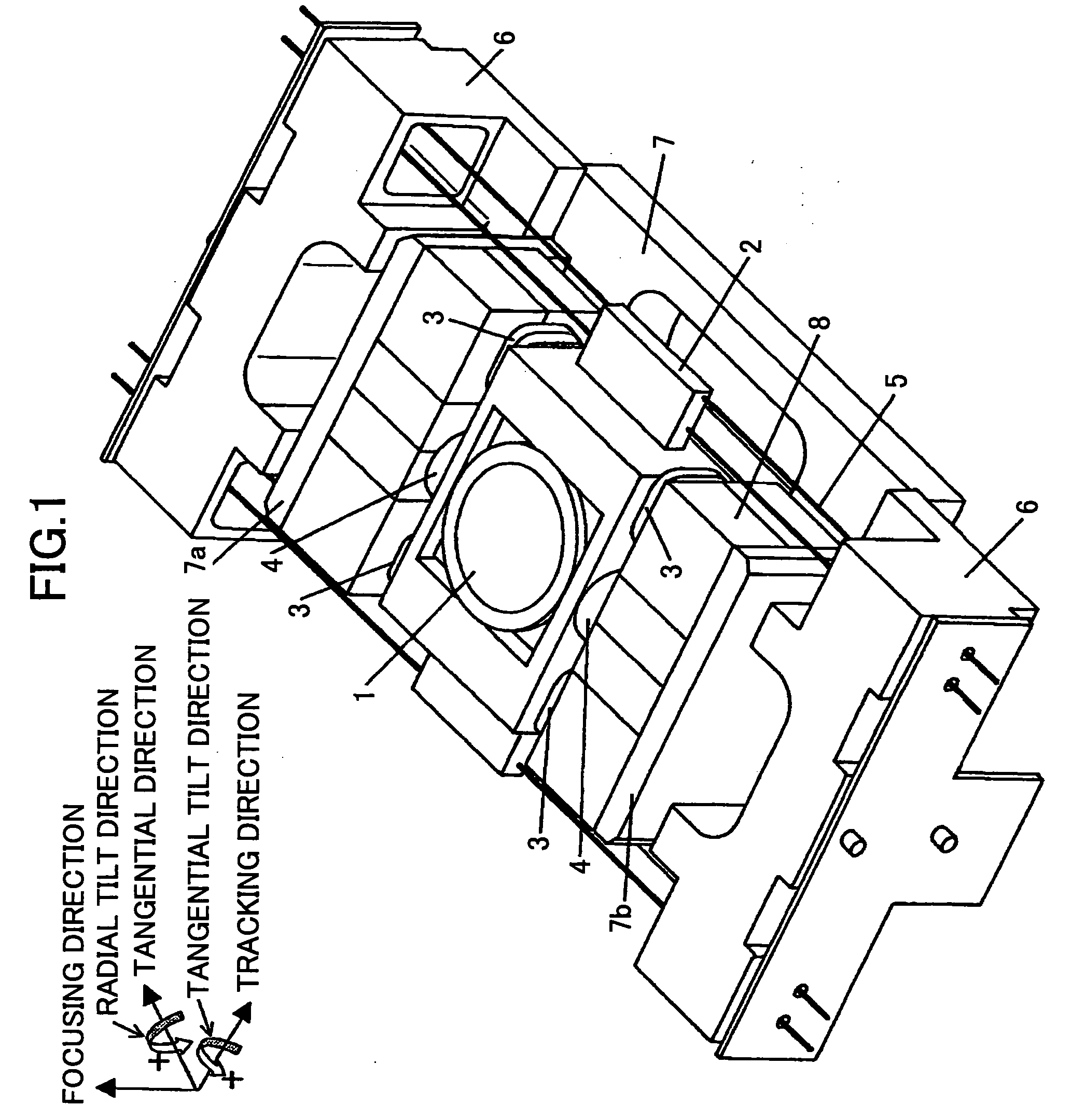
[0094]FIG. 1 is a perspective view illustrating an object lens driving device according to a first embodiment of the present invention.

[0095] The structure shown in FIG. 1 includes an object lens 1, an object lens holding member 2, focus driving coils (abbreviated to be “Fo coil” hereinafter) 3, a track driving coil (abbreviated to be “Tr coil” hereinafter) 4, wire springs 5, fixed members 6, a base 7, driving magnets 8, and a radial tilt driving coil 9.

[0096] A hole is formed at the center of the base 7, and on two sides of the hole, walls 7a, 7b are formed to face each other. On the side surfaces of the base 7, two fixed members 6 are provided to sandwich the walls 7a, 7b. Two driving magnets 8 are attached to the walls 7a, 7b, respectively. Between the two driving magnets 8, the object lens holding member 2 is arranged to hold the object lens 1.

[0097] The object lens holding member 2 is nearly a rectangle having a hole at the center, and the object lens 1 is mounted on the hol...

second embodiment

[0120]FIG. 5 is a perspective view illustrating an object lens driving device according to a second embodiment of the present invention.

[0121] The object lens driving device according to the present embodiment basically has the same structure as that of the first embodiment as shown in FIG. 1, except for the shape of the hole in the base 7, the configuration of the driving magnets 8, and the arrangement of the driving coils. Below, the same reference numbers are assigned to the same elements as those described in the first embodiment, and overlapping descriptions are omitted.

[0122]FIG. 6 is a plan view illustrating a structure of the driving motor in the object lens driving device in FIG. 5.

[0123] As illustrated in FIG. 5, the driving magnet 8 has four magnetization regions, which are defined by two lines forming a cross, including a boundary line passing through the center of the driving magnet 8 and parallel to the focusing direction, and a boundary line passing through the cen...

third embodiment

[0130]FIG. 9 is a perspective view illustrating an object lens driving device according to a third embodiment of the present invention.

[0131] The object lens driving device according to the present embodiment basically has the same structure as that of the first embodiment as shown in FIG. 1, except for the configuration of the driving magnet 8 and arrangement of the driving coils. Below, the same reference numbers are assigned to the same elements as those described in the first embodiment, and overlapping descriptions are omitted.

[0132]FIG. 10 is a plan view illustrating a structure of the driving motor in the object lens driving device in FIG. 9.

[0133] As illustrated in FIG. 10, the driving magnet 8 has three magnetization regions, which are defined by an L-shaped boundary line including a section extending to the center of the driving magnet 8 and parallel to the focusing direction and a section extending to the center of the driving magnet 8 and parallel to the tracking dire...


PUM

PropertyMeasurementUnit
thrust forceaaaaaaaaaa
magnetic flux density distributionsaaaaaaaaaa
driving forcesaaaaaaaaaa

Abstract

An object lens driving device is disclosed that has a small tilt even when focusing and tracking operations are performed at the same time. A movable unit including an object lens holding member with an object lens, focus coils and track coils attached thereon is supported by two sets of four wire springs, totaling eight wire springs, connected to fixed units on two sides of the object lens holding member in the tangential direction. When the movable unit is set to face a driving magnet which has a boundary line at the center portion of the magnet and parallel to the focusing direction, and boundary lines at two ends of the magnet and parallel to the tracking direction, the interval Lc_Fo between centers of the focus coils in the tracking direction is less than the interval Lm_Fo between centers of magnetic flux density distributions of the magnet. Consequently, a moment is generated to cancel out a tilt of the movable unit occurring in a supporting system when the movable unit moves in the focusing direction and the tracking direction.

Description

BACKGROUND OF THE INVENTION [0001] 1. Field of the Invention [0002] The present invention relates to a driving device of an object lens in an optical disk drive or a magneto-optic disk drive, an optical pickup, and an optical disk drive. [0003] 2. Description of the Related Art [0004] In an optical disk drive, a laser beam is emitted onto an optical disk, which acts as a recording medium, and information recorded in the optical disk is extracted from light reflected by the optical disk. An object lens driving device installed in the optical disk drive controls the object lens so that the object lens follows up wobble or eccentricity of the recording medium so as to drive the object lens in a focusing direction and a tracking direction and form a light spot on a recording surface of the recording medium. [0005] When dealing with data of a large size, it is desirable that recording and reproduction be carried out at high speed, and for this purpose, it is necessary to drive the record...

Claims


Application Information

Patent Timeline
Patent Type & Authority Applications(United States)
IPC IPC(8): G11B7/08G11B7/085G11B7/09G11B7/095
CPCG11B7/0932G11B7/0956G11B7/0935G11B7/0933
Inventor AKANUMA, GOICHI
Owner RICOH KK
Why Eureka
Try Eureka