Multilayer optical bodies

a light-reflecting optical body and multi-layer technology, applied in the field of multi-layer light-reflecting optical bodies, can solve the problems of limited optical performance for a given number of layers, limited thermal stability, dimensional stability, environmental stability and/or solvent resistance, and relatively expensive materials that are difficult to protect from ultraviolet radiation

Inactive Publication Date: 2005-08-25
3M INNOVATIVE PROPERTIES CO
View PDF90 Cites 35 Cited by
  • Summary
  • Abstract
  • Description
  • Claims
  • Application Information

AI Technical Summary

Problems solved by technology
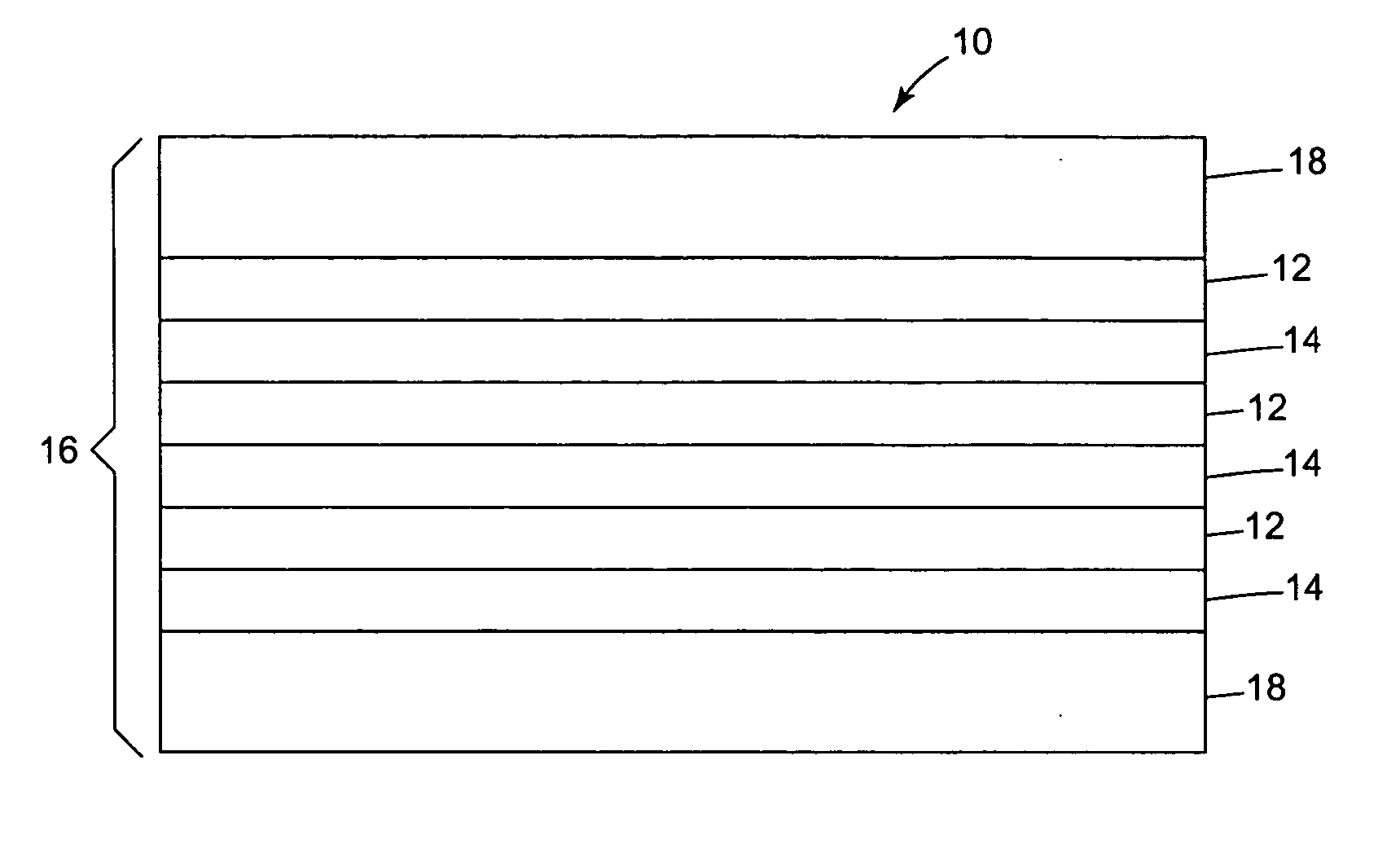
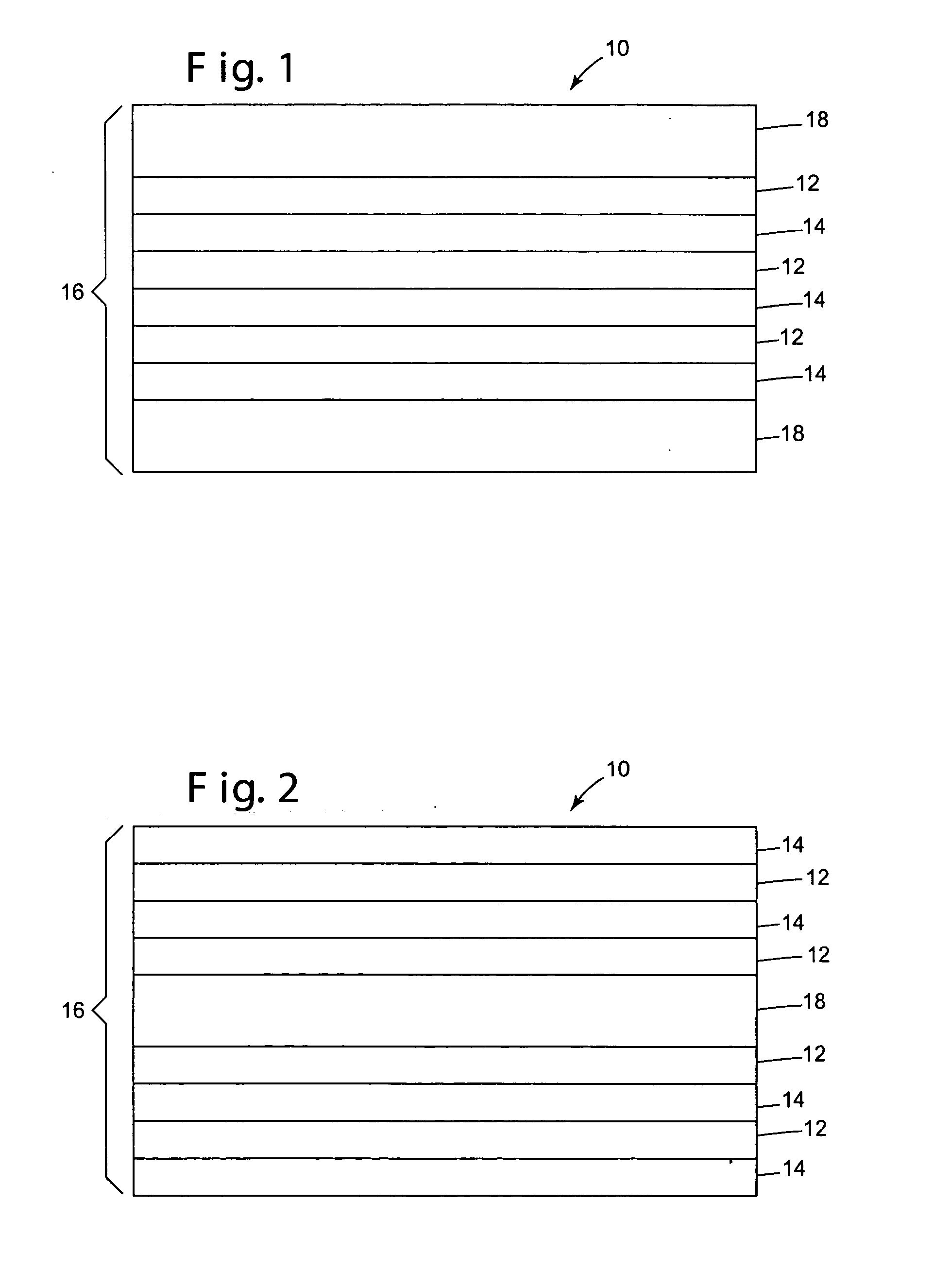
Generally, however, cast films have a number of practical drawbacks.
For example, cast films generally have low refractive index differences between the high and low index materials and do not generally have matching refractive indices in the z-direction, limiting the optical performance for a given number of layers.
Moreover, some cast films, particularly films made of noncrystalline materials, can also have limited thermal stability, dimensional stability, environmental stability and / or solvent resistance.
PEN, however, is a relatively expensive material which is difficult to protect from ultraviolet radiation, and polyethylene terephthalate (PET), a lower index alternative to PEN, cannot easily be suitably oriented with PMMA due to the difference in glass transition temperatures of these materials (about 84° C. for PET and about 106° C. for PMMA).

Method used


Image

  • Multilayer optical bodies
  • Multilayer optical bodies
  • Multilayer optical bodies

Examples


example 1

[0123] Color-shifting Optical Film with PET:MMA-EA Layers. An optical film was constructed with first optical layers created from polyethylene terephthalate (PET) and second optical layers created from a copolymer using 75 wt. % methylmethacrylate (MMA) monomers and 25 wt. % of ethyl acrylate (EA) monomers. The copolymer is available under the product designation “Perspex™ CP63” from ICI Americas, Inc. (Wilmington, Del.).

[0124] The above described polymers were then coextruded through a multilayer melt manifold to create a multilayer film with 224 alternating first and second optical layers of a total thickness of about 580 μm. This particular multilayer reflective film also contained external protective layers made of the same polyethylene terephthalate as the first optical layers approximately 145 μm thick on each side. The optical film was initially preheated, then stretched in the machine direction to a ratio of 3.7:1 at approximately 85° C., and then stretched in the transvers...

example 2

[0127] Color-Shifting Optical Film with PET:MMA-EA Layers. This optical film was made in the same way as the optical film of Example 1, except that during the drawing process, the optical film was initially preheated to 94° C. for 1 minute, then biaxially stretched at a 3.4:3.4 ratio at 94° C. at a draw rate of 20% / s.

[0128] The PET first optical layers were oriented by the process as determined by refractive index measurement of the external protective PET layers (nMD=1.6173, nTD=1.6197, nz=1.5108). The second optical layers were essentially isotropic with a refractive index of about 1.49.

[0129] The optical film had the transmission spectrum illustrated in FIG. 5 for normally incident light. The optical film had a blue appearance that changed to red as the viewing angle increased with respect to normal incidence.

example 3

[0130] Color-Shifting Optical Film with PET:MMA-EA Layers. This optical film was made in the same way as the optical film of Example 1, except that during the drawing process, the optical film was initially preheated to 84° C. for 1 minute, then biaxially stretched at a 2.4:2.4 ratio at 84° C. at a draw rate of 20% / s.

[0131] The PET first optical layers were oriented by the process as determined by refractive index measurement of the external protective PET layers (nMD=1.6121, nTD=1.6107, nz=1.5200). The second optical layers were essentially isotropic with a refractive index of about 1.49.

[0132] The optical film had the transmission spectrum illustrated in FIG. 6 for normally incident light. The optical film had a red appearance that changed to yellow as the viewing angle increased with respect to normal incidence.


PUM

PropertyMeasurementUnit
refractive indicesaaaaaaaaaa
glass transition temperaturesaaaaaaaaaa

Abstract

Optical bodies, comprising: a plurality of first optical layers comprising a first polymer composition that comprises (i) a polyester portion having terephthalate comonomer units and ethylene glycol comonomer units; and (ii) a second portion corresponding to a polymer having a glass transition temperature of at least about 130° C.; and a plurality of second optical layers disposed in a repeating sequence with the plurality of first optical layers. Also disclosed are optical bodies comprising: (a) a plurality of first optical layers, each first optical layer being oriented; and (b) a plurality of second optical layers, disposed in a repeating sequence with the plurality of first optical layers, comprising a blend of polymethylmethacrylate and polyvinylidene fluoride. Methods of making the above-described optical bodies, and articles employing such optical bodies are also provided.

Description

[0001] This patent application is a continuation of U.S. patent application Ser. No. 10 / 215,791, filed Aug. 9, 2002, which is a continuation of U.S. patent application Ser. No. 09 / 444,756, filed Nov. 22, 1999, now U.S. Pat. No. 6,498,683, both of which are incorporated herein by reference. This patent application is also a continuation-in-part of U.S. patent application Ser. No. 10 / 654,348, filed Sep. 2, 2003, which is a division of U.S. patent application Ser. No. 09 / 962,748, filed Sep. 25, 2001, and now issued as U.S. Pat. No. 6,613,421, which is a division of U.S. patent application Ser. No. 09 / 527,452, filed Mar. 17, 2000, and now issued as U.S. Pat. No. 6,296,927, which is a division of U.S. patent application Ser. No. 09 / 145,371, filed Sep. 2, 1998, and now issued as U.S. Pat. No. 6,117,530, which is a continuation of U.S. patent application Ser. No. 08 / 402,041, filed Mar. 10, 1995, and now issued as U.S. Pat. No. 5,882,774, which is a continuation-in-part of U.S. patent appli...

Claims


Application Information

Patent Timeline
Patent Type & Authority Applications(United States)
IPC IPC(8): B29C55/02B29D11/00B32B7/023B32B27/08B32B27/36C08L27/16C08L33/12G02B5/08G02B5/26G02B5/28G02B5/30G02B27/28G02F1/1335G02F1/13357
CPCB29C55/023Y10T428/24942B29K2995/003B29K2995/0034B32B7/02B32B27/08B32B27/36G02B5/0841G02B5/26G02B5/287G02B5/3025G02B5/3041G02B5/305G02B5/3083G02B27/283G02F1/133536G02F1/13362G02F2001/133545Y10S428/91B29D11/00Y10T428/31797Y10T428/31935Y10T428/3154Y10T428/31786G02F1/133545B32B7/023G02B5/08B32B2307/416B32B2307/42B32B2551/00B32B2551/08
Inventor CONDO, PETER D.HEBRINK, TIMOTHY J.WHEATLY, JOHN A.OUDERKIRK, ANDREW J.RUFF, ANDREW T.ANDRUS, MILTON H. JR.
Owner 3M INNOVATIVE PROPERTIES CO
Why Eureka
Try Eureka