Novel thin laminate as embedded capacitance material in printed circuit boards

a capacitance material and printed circuit board technology, applied in the direction of fixed capacitors, solid-state devices, synthetic resin-layered products, etc., can solve the problems of poor dielectric strength, low dielectric constant, and limited performance of capacitors of this typ

Active Publication Date: 2005-08-25
MITSUI MINING & SMELTING CO LTD
View PDF11 Cites 29 Cited by
  • Summary
  • Abstract
  • Description
  • Claims
  • Application Information

AI Technical Summary

Problems solved by technology

However, the performance of capacitors of this type has been limited by factors such as the limited minimum thickness of the dielectric material, which detracts from the flexibility of the capacitor and attainable capacitance, the effect of bond enhancers on the metal foils, low dielectric constant and poor di

Method used


Image

  • Novel thin laminate as embedded capacitance material in printed circuit boards

Examples


example 1

[0052] A roll of one ounce electrodeposited copper foil, 35 micron thickness, 0.64 meters in width is mounted on an unwinding roller of a coating machine. A sample of foil 0.64×0.1 m2 is taken and measured using a micrometer (capable of measuring 0.05 micron) to establish the foil thickness. The foil is threaded through tensioning rollers and into an oven through idler rollers and onto rewind rollers. The foil is tensioned to 0.7 kg per centimeter. Temperatures of the air oven dryer are set at 90° C., 120° C., and 150° C. in three different zones and allowed to stabilize. A drive motor is engaged on the rewind roller and the line speed is set to 2 m / min. A liquid epoxy resin is adjusted to 30% solids, a viscosity of about 300 centipoises, with methyl-ethyl ketone in a stainless steel mixing vat.

[0053] The gap between coating die and foil is adjusted to produce a wet film on the foil, resulting in a coated foil having a 7 μ thick dried polymer film. A constant flow, pump pressure an...


PUM

PropertyMeasurementUnit
Temperatureaaaaaaaaaa
Fractionaaaaaaaaaa

Abstract

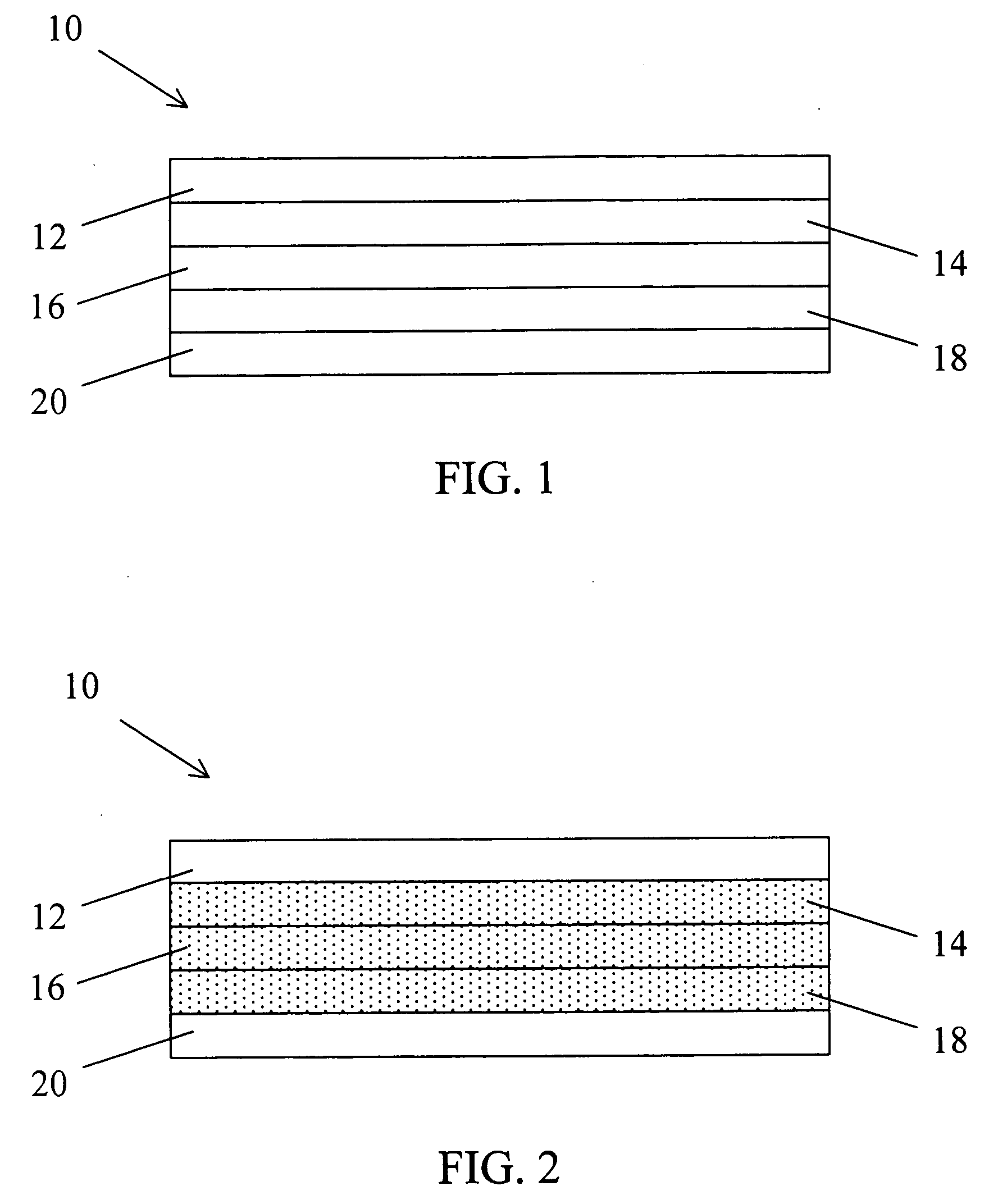
The invention concerns multilayered structures useful for forming capacitors, which may be embedded within printed circuit boards or other microelectronic devices. The multilayered structure comprises a pair of parallel electrically conductive layers separated by a pair of dielectric layers and a central polymerizable layer. Each of the dielectric layers and the central layer may include a filler. Capacitors formed from the multilayered structures of the invention exhibit excellent short circuit resistance as well as excellent void resistance.

Description

BACKGROUND OF THE INVENTION [0001] 1. Field of the Invention [0002] This invention relates to structures suitable for forming capacitors. More particularly, this invention pertains to capacitors embedded within printed circuit boards or other microelectronic devices. The capacitor comprises a pair of parallel electrically conductive foils separated by a pair of coatings of a thermosetting polymer and a central polymerizable layer, each of which preferably contain a filler material. The capacitor exhibits excellent capacitance density and short circuit resistance. [0003] 2. Description of the Related Art [0004] A capacitor is a device used for introducing capacitance into a circuit, and functions primarily to store electrical energy, block the flow of direct current, or permit the flow of alternating current. They generally comprise a dielectric material sandwiched between two electrically conductive metal layers, such as copper foils. Such dielectric materials may be coupled to the ...

Claims


Application Information

Patent Timeline
IPC IPC(8): B32B15/08B32B15/20B32B27/20B32B27/34B32B27/38H01G4/20H01L21/48H01L23/498H01L23/64H05K1/16
CPCB32B15/08Y10T428/12569B32B27/20B32B27/34B32B27/38H01G4/203H01L21/4857H01L23/49822H01L23/642H05K1/162H05K2201/0195H05K2201/0209H05K2201/0355H05K2201/09309H01L2924/0002B32B15/20Y10T428/12549Y10T428/12535H01L2924/00Y10T428/31511Y10T428/31522Y10T428/31605Y10T428/31681Y10T428/31688Y10T428/31692Y10T428/31725Y10T428/31786
Inventor PRAMANIK, PRANABES K.
Owner MITSUI MINING & SMELTING CO LTD
Why Eureka
Try Eureka