Method and apparatus for signal phase locking

a signal phase and locking technology, applied in the field of ac devices, can solve the problems of single-phase electrical system vulnerability, noise occurring in the vicinity of the applicator,

Active Publication Date: 2005-08-25
SQUARE D CO
View PDF6 Cites 62 Cited by
  • Summary
  • Abstract
  • Description
  • Claims
  • Application Information

AI Technical Summary

Problems solved by technology

Such approaches are not amenable to single-phase electrical systems.
Under nominal conditions, zero crossing detection provides a straightforward means of phase / frequency locking, but the approach suffers from its vulnerability to noise occurring at or around the zero crossing points.

Method used


Image

  • Method and apparatus for signal phase locking
  • Method and apparatus for signal phase locking
  • Method and apparatus for signal phase locking

Examples


Embodiment Construction

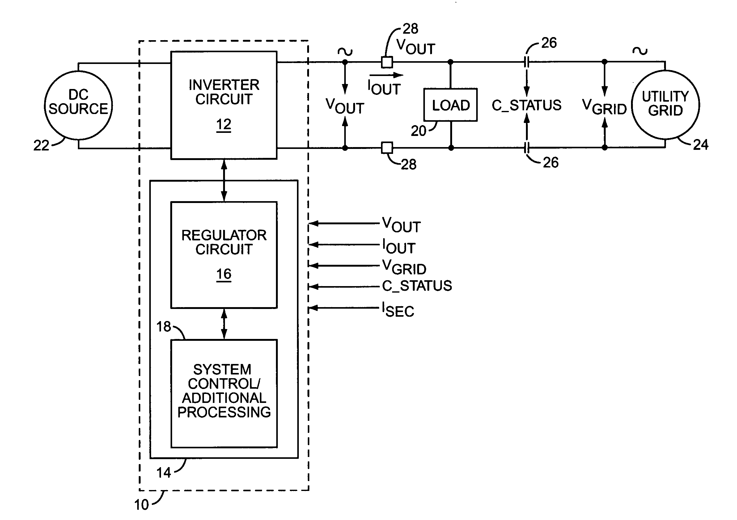
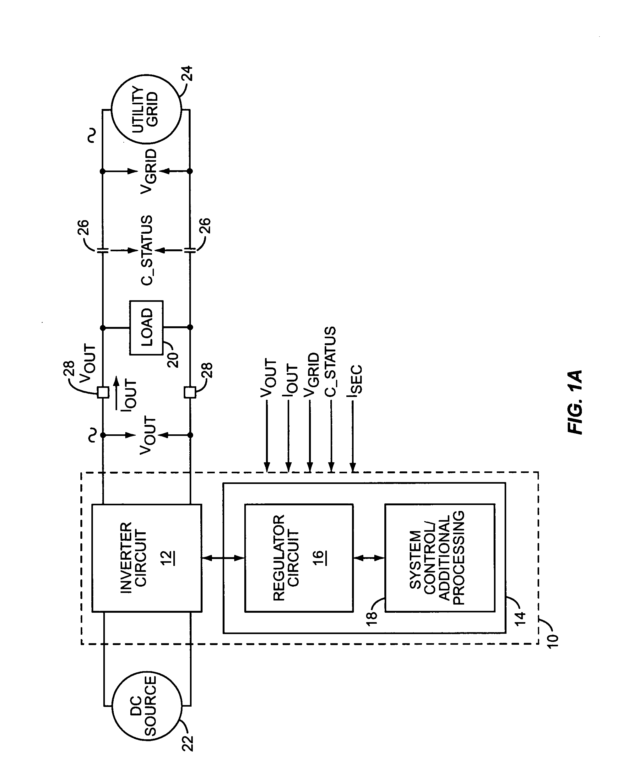
[0021] In one or more exemplary embodiments, the present invention comprises a PLL circuit that enables an ac device to lock with an electrical system voltage. FIG. 1A illustrates an exemplary ac power inverter 10 in which the present invention can be practiced. Inverter 10 comprises an inverter circuit 12 and a control circuit 14, which can include multiple functional circuits, including a regulator circuit 16, and one or more additional processing and system control circuits 18. While not limited to such configurations, an exemplary PLL circuit according to the present invention is implemented within the digital signal processing logic of control circuits 18.

[0022] Inverter 10 provides ac power to a load 20 based on converting dc power provided by a local dc source 22 into ac power at the desired voltage and frequency. The load 20 can be connected in parallel with an external power system 24, e.g., a utility grid, through contactors 26. Complementing its operation in this arrange...


PUM


Abstract

A phase locked loop (PLL) circuit provides ac devices, such as power inverters and power measurement devices, with a reliable means for synchronizing to ac electrical systems. In an exemplary embodiment, the PLL circuit is configured for operation with single-phase electrical systems and offers substantial noise immunity by basing its locking operations on measured fundamental components, i.e., measured x-y phasors, of the electrical system voltage. Further, with its phasor-based locking operations and with its timer / counter-based operation, the PLL circuit can be implemented partly or wholly in digital processing logic.

Description

BACKGROUND OF THE INVENTION [0001] The present invention generally relates to ac devices, and particularly relates to synchronizing the operation of such devices to ac electrical systems. [0002] Power measurement devices, such as electronic metering devices, are commonplace, and power conversion devices, such as dc-ac power inverters, are becoming more commonplace with the increased interest in alternative energy systems to provide localized power generation. Characteristically, these devices must synchronize themselves to an electrical system of interest. For example, electronic power meters synchronize their measurement operations with respect to the electrical system supplying the measured power. Similarly, localized alternative energy systems often are required to operate in grid-connected modes, wherein they are interconnected with an external electrical system, such as a utility company's power distribution grid. [0003] Thus, there is a need for these ac electrical devices to ...

Claims


Application Information

Patent Timeline
Patent Type & Authority Applications(United States)
IPC IPC(8): G06F17/50H02M7/538H03L7/08
CPCH03L7/08H02M7/53806
Inventor COLBY, ROY STEPHENKOCHER, MARK JOHNCARSON, GERALD BENJAMIN
Owner SQUARE D CO
Why Eureka
Try Eureka