Air conditioning system for vehicle

a technology for air conditioning systems and vehicles, applied in domestic cooling devices, indirect heat exchangers, lighting and heating devices, etc., can solve the problems of increased manufacturing costs, increased manufacturing costs, and worsening of passenger cooling operations, so as to improve high durability and reliability, the effect of low manufacturing costs

Inactive Publication Date: 2005-09-01
DENSO CORP
View PDF2 Cites 28 Cited by
  • Summary
  • Abstract
  • Description
  • Claims
  • Application Information

AI Technical Summary

Benefits of technology

[0016] The present invention is made in view of the above problems, and it is an object of the present invention to provide an air conditioning system of a cool storage type for a vehicle. The air conditioning system of the present invention is simple in structure and low in manufacturing cost, and further has an improved high durability and reliability by eliminating the mechanical pump driven by the electric motor.

Problems solved by technology

Accordingly, a feeling of a cooling operation for the passenger would become worse.
And thereby, it has a disadvantage in that a manufacturing cost is increased.
Furthermore, there are following disadvantages, in the case that the electrically driven pump would be installed within the liquid refrigerant storing tank to improve an installing process of the air conditioning system into a vehicle:
As a result, the manufacturing cost is increased and an additional space for the gas-liquid separating tank is necessary.
The manufacturing cost is thereby further increased.

Method used


Image

  • Air conditioning system for vehicle
  • Air conditioning system for vehicle
  • Air conditioning system for vehicle

Examples


first embodiment

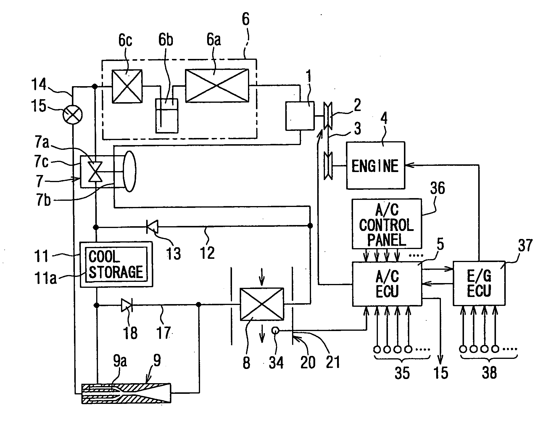
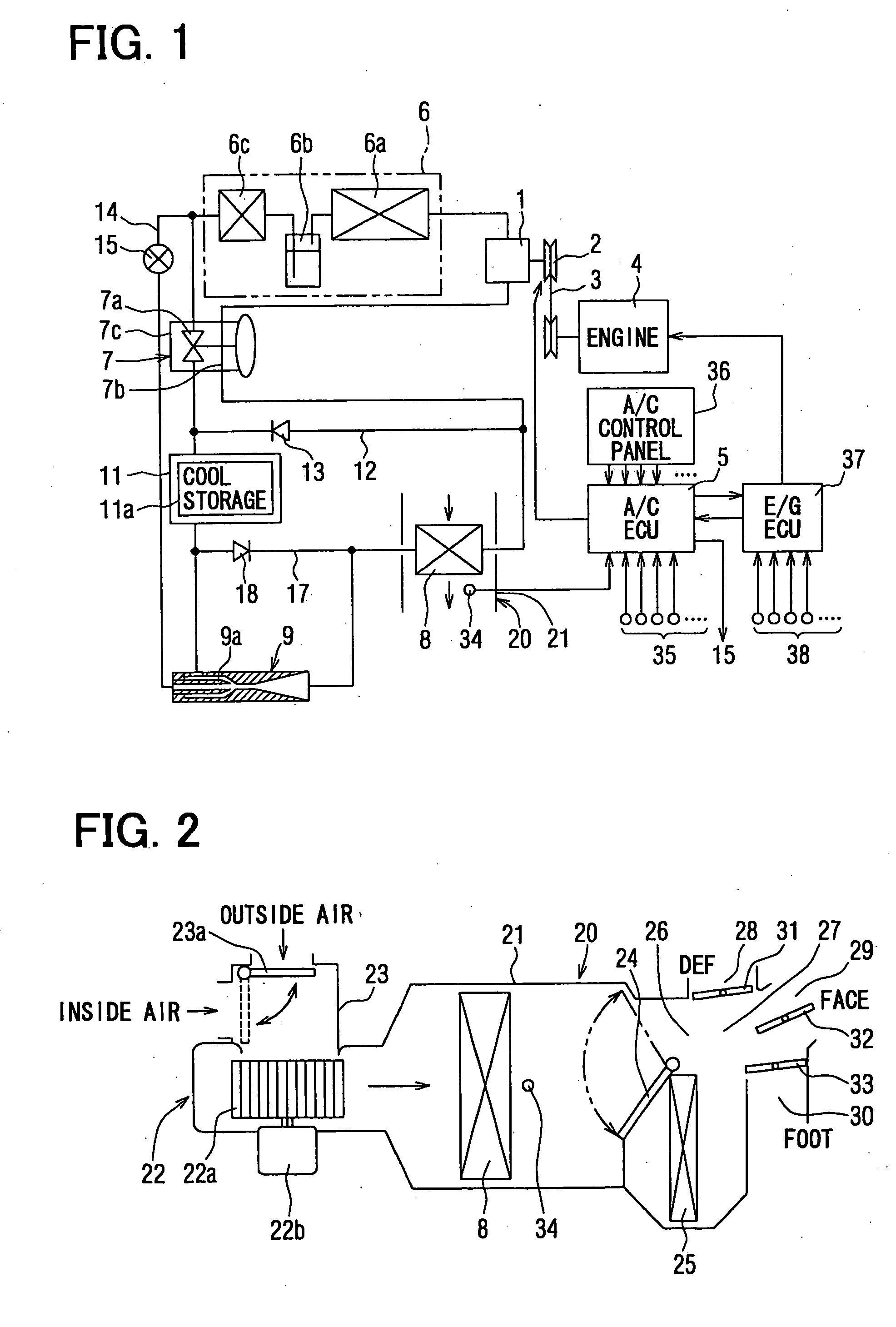
[0049] The present invention will be explained below with reference to the embodiments. FIG. 1 is a schematic view of an air conditioning system for a vehicle according to a first embodiment of the present invention. The air conditioning system is installed, for example in a hybrid vehicle, in which an internal combustion engine is operated or stopped depending on a running mode of the vehicle, or in such a vehicle having an economical-running function, in which an operation of an internal combustion engine is temporarily stopped at a vehicle stop in case of waiting for a change of a traffic lamp.

[0050] A refrigerating cycle for the air conditioning system comprises a compressor 1 for sucking, compressing and discharging a refrigerant, wherein the compressor 1 is equipped with an electromagnetic clutch 2. The compressor 1 is operatively connected with an internal combustion engine 4 via the clutch 2 and a belt 3, so that an operation of the compressor 1 is controlled by the electro...

second embodiment

[0102] A second embodiment of the present invention is explained with reference to FIG. 8 and FIG. 9, which schematically show the refrigerating cycle.

[0103] In the second embodiment, the bypass flow passage 12 (of the first embodiment) is eliminated, and instead a suction flow passage 16 is provided between the suction port of the ejector 9 and the inlet side of the compressor 1 (the outlet side of the evaporator 8). Further, the pressure increasing portion (the outlet port) of the ejector 9 is connected to the upstream side of the cool storage heat exchanger 11 through the check valve 13.

[0104] As shown in FIG. 8, in the normal cooling operation (and the operation for storing the cooling energy), the refrigerating cycle is operated by the compressor 1, so that the refrigerant flows from and to the compressor 1 through the condenser device 6, the expansion valve 7, the cool storage heat exchanger 11, and the evaporator 8. In this operation, since the operation of the ejector 9 is...

third embodiment

[0109] A third embodiment of the present invention is explained with reference to FIGS. 10 and 11, which schematically show the refrigerating cycle.

[0110] In the first or second embodiment, the expansion valve 7 is used as a depressurizing means, and the degree of the super heat of the refrigerant at the outlet of the evaporator 8 is controlled by the expansion valve 7.

[0111] According to the third embodiment, an accumulator 100 is provided at the outlet side of the evaporator 8 (the inlet side of the compressor 1) for separating the refrigerant from the evaporator 8 into the gas-phase and the liquid-phase refrigerant, for storing the separated refrigerant, and for supplying the gas-phase refrigerant to the compressor 1. The above refrigerating cycle is also referred to as “the refrigerating cycle of accumulator type” or “the accumulator cycle”. Further, a fixed orifice 70, such as a capillary tube orifice, is provided as the depressurizing means instead of the expansion valve 7. ...


PUM


Abstract

An air conditioning system for a vehicle has a cool storage heat exchanger for continuing cooling operation with stored cooling energy during a compressor is stopped due to a temporal stop of an engine for the vehicle. Cooling energy is stored in the cool storage material of the cool storage heat exchanger during a normal cooling operation during which the compressor is operated by the engine. When the vehicle stops, for example before a traffic lamp, and thereby the compressor is not operated, an ejector is operated to circulate the refrigerant from the cool storage heat exchanger to an evaporator so that the cooling operation can be continued.

Description

CROSS REFERENCE TO RELATED APPLICATION [0001] This application is based on Japanese Patent Application Nos. 2004-54667 filed on Feb. 27, 2004 and 2005-004450 filed on Jan. 11, 2005, the disclosures of which are incorporated herein by reference. FIELD OF THE INVENTION [0002] This invention relates to an air conditioning system for a vehicle, and more particularly to an air conditioning system for a motor vehicle, in which an internal combustion engine for driving a compressor as well as the vehicle is temporarily stopped when a certain condition is met, for example at a vehicle stop. BACKGROUND OF THE INVENTION [0003] In recent years, such a vehicle as an economical-running vehicle, for example a hybrid car, in which an operation of an internal combustion engine is temporarily stopped at a vehicle stop in case of waiting for a change of a traffic lamp, is realized, in view of an environment protection, an improvement of a fuel consumption ratio and so on. And a demand for such vehicl...

Claims


Application Information

Patent Timeline
Patent Type & Authority Applications(United States)
IPC IPC(8): B60H1/32F25B1/00F25B1/06F25B7/00F25B13/00B60H1/00F25B41/00F25D3/00F25D16/00F25D17/02
CPCB60H2001/3298F25B41/00F25B2341/0011F25D16/00F25B2400/23F25B2400/24F25B2700/21173F25B2341/0012F28D20/021Y02E60/14
Inventor AIKAWA, YASUKAZUYAMADA, ETSUHISAINABA, ATSUSHIHISANAGA, SHIGERUTAKEUCHI, HIROTSUGU
Owner DENSO CORP
Why Eureka
Try Eureka