Azimuthal binning of density and porosity data

a density and porosity data and azimuthal binning technology, applied in the field of borehole logging apparatus and methods, can solve the problems of loss of drilling time, cost and delay involved, and measurement is typically carried ou

Active Publication Date: 2005-09-01
BAKER HUGHES INC
View PDF18 Cites 25 Cited by
  • Summary
  • Abstract
  • Description
  • Claims
  • Application Information

AI Technical Summary

Problems solved by technology

Such “wireline” measurements are normally done in real time (however, these measurements are taken long after the actual drilling has taken place).
Wireline formation evaluation tools such as the aforementioned gamma ray density tools have many drawbacks and disadvantages including loss of drilling time, the expense and delay involved in tripping the drillstring so as to enable the wireline to be lowered into the borehole and both the build up of a substantial mud cake and invasion of the formation by the drilling fluids during the time period between drilling and taking measurements.
One potential problem with MWD logging tools is that the measurements are typically made while the tool is rotating.
Nuclear measurements are particularly degraded by large standoffs due to the scattering produced by borehole fluids between the tool and the formation.
A drawback of the Holenka method is that the assumption of minimum standoff is not necessarily satisfied, so that the down position may in fact correspond to a significant standoff: without a standoff correction and the results may be erroneous.
In the absence of standoff corrections, this can only be a qualitative measurement and the absolute density measurements may be suspect.
This may result in decreased vertical resolution.

Method used


Image

  • Azimuthal binning of density and porosity data
  • Azimuthal binning of density and porosity data
  • Azimuthal binning of density and porosity data

Examples


Embodiment Construction

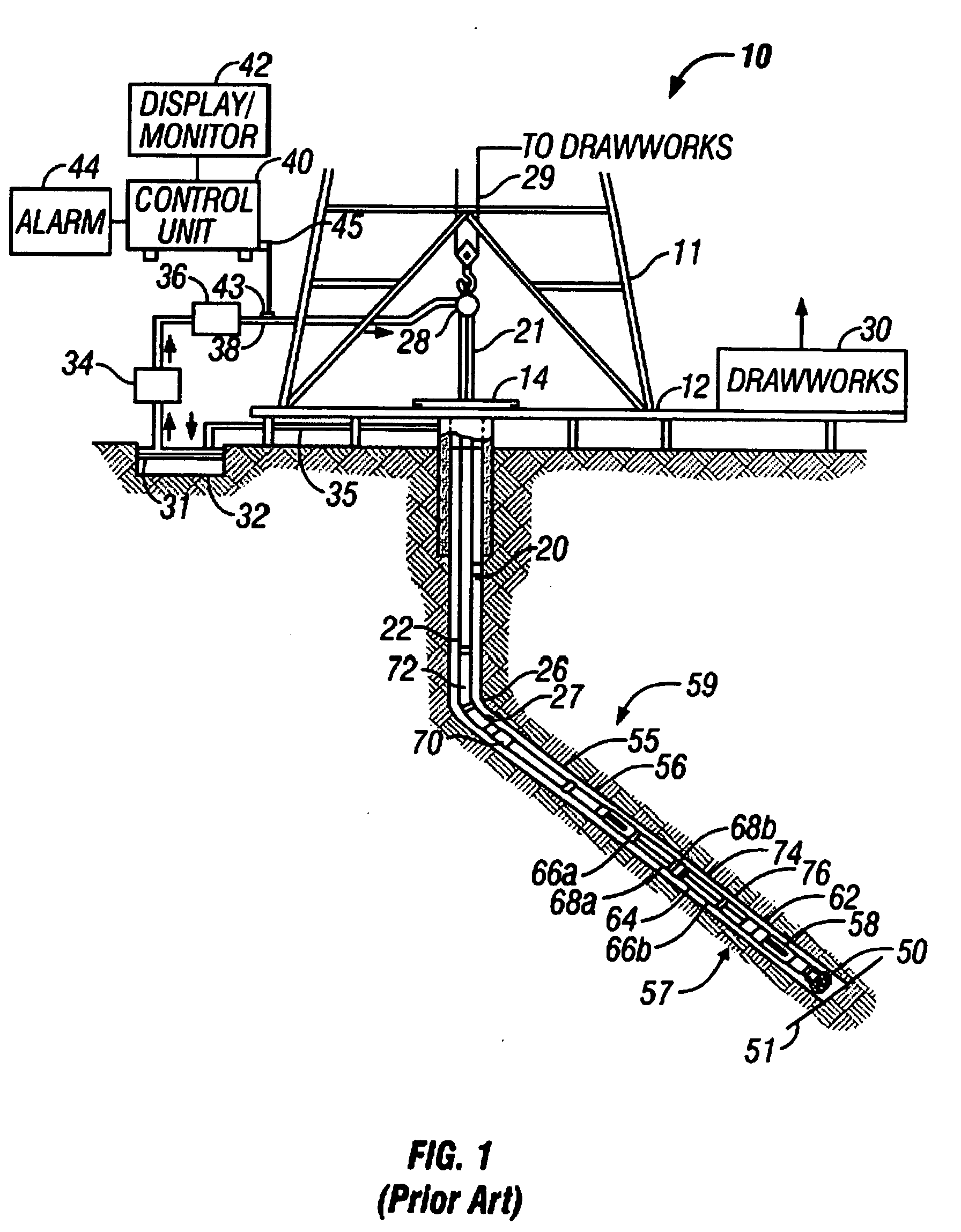
[0025]FIG. 1 shows a schematic diagram of a drilling system 10 having a downhole assembly containing an acoustic sensor system and the surface devices according to one embodiment of present invention. As shown, the system 10 includes a conventional derrick 11 erected on a derrick floor 12 which supports a rotary table 14 that is rotated by a prime mover (not shown) at a desired rotational speed. A drill string 20 that includes a drill pipe section 22 extends downward from the rotary table 14 into a borehole 26. A drill bit 50 attached to the drill string downhole end disintegrates the geological formations when it is rotated. The drill string 20 is coupled to a drawworks 30 via a kelly joint 21, swivel 28 and line 29 through a system of pulleys 27. During the drilling operations, the drawworks 30 is operated to control the weight on bit and the rate of penetration of the drill string 20 into the borehole 26. The operation of the drawworks is well known in the art and is thus not des...


PUM


Abstract

A logging-while-drilling density sensor includes a gamma ray source and at least two NaI detectors spaced apart from the source for determining measurements indicative of the formation density. A magnetometer on the drill collar measures the relative azimuth of the NaI detectors. Measurements made by the detectors are partitioned into bins defined by azimuth. A compensated bulk density is determined for selected ones of said azimuthal sectors that meet a threshold test related to a minimum difference of measurements or a minimum correction. The method of the invention may also be used with neutron porosity logging devices.

Description

CROSS-REFERENCES TO RELATED APPLICATIONS [0001] This applications claims priority from U.S. Provisional Patent Application Ser. No. 60 / 547838 filed on Feb. 26, 2004.BACKGROUND OF THE INVENTION [0002] 1. Field of the Invention [0003] This invention relates generally to borehole logging apparatus and methods for performing nuclear radiation based measurements. More particularly, this invention relates to a new and improved apparatus for effecting formation density logging in real time using gamma rays in a measurement-while-drilling (MWD) tool. [0004] 2. Background of the Art [0005] Oil well logging has been known for many years and provides an oil and gas well driller with information about the particular earth formation being drilled. In conventional oil well logging, after a well has been drilled, a probe known as a sonde is lowered into the borehole and used to determine some characteristic of the formations which the well has traversed. The probe is typically a hermetically seale...

Claims


Application Information

Patent Timeline
Patent Type & Authority Applications(United States)
IPC IPC(8): G01V5/12
CPCG01V5/125
Inventor SALE, MATTHEW J.
Owner BAKER HUGHES INC
Why Eureka
Try Eureka