Erasing device

a radiation energy and erasing technology, applied in the direction of material analysis using wave/particle radiation, instruments, material analysis by optical means, etc., can solve the problems of degrading requiring a long time to finish the erasing process, and the radiation image information recorded on the stimulable phosphor panel may not be read and displayed properly, so as to reduce the amount of energy and processing time, and achieve efficient and reliable erasing

Inactive Publication Date: 2005-09-01
FUJIFILM HLDG CORP +1
View PDF4 Cites 2 Cited by
  • Summary
  • Abstract
  • Description
  • Claims
  • Application Information

AI Technical Summary

Benefits of technology

[0010] It is a general object of the present invention to provide an erasing device for erasing radiation energy remaining in a stimulable phosphor panel with a minimum amount of erasing light required thereby to reduce the amount of energy and the processing time required to erase the remaining radiation energy and to erase the radiation energy efficiently and reliably.

Problems solved by technology

If remaining radiation energy on the stimulable phosphor panel is not fully erased, then next radiation image information recorded on the stimulable phosphor panel may not be read and displayed properly.
However, simply increasing the amount of erasing light applied to the stimulable phosphor panel tends to degrade the stimulable phosphor panel by the heat of the erasing light and a long period of time to finish the erasing process is required.
Even if a required amount of erasing light is applied to a stimulable phosphor panel to erase remaining radiation energy therefrom, it is not guaranteed that no radiation energy remains on the stimulable phosphor panel in a next radiation image exposure process.
Natural radiation applied while the stimulable phosphor panel is in storage may appear as noise.
Since the application of erasing light in an amount greater than necessary to a stimulable phosphor panel consumes wasteful energy for erasing remaining radiation energy from the stimulable phosphor panel or needs a long period of time until remaining radiation energy is erased from the stimulable phosphor panel, an amount of erasing light to be applied to the stimulable phosphor panel has to be selected in view of these undesirable factors.

Method used


Image

  • Erasing device
  • Erasing device
  • Erasing device

Examples


Embodiment Construction

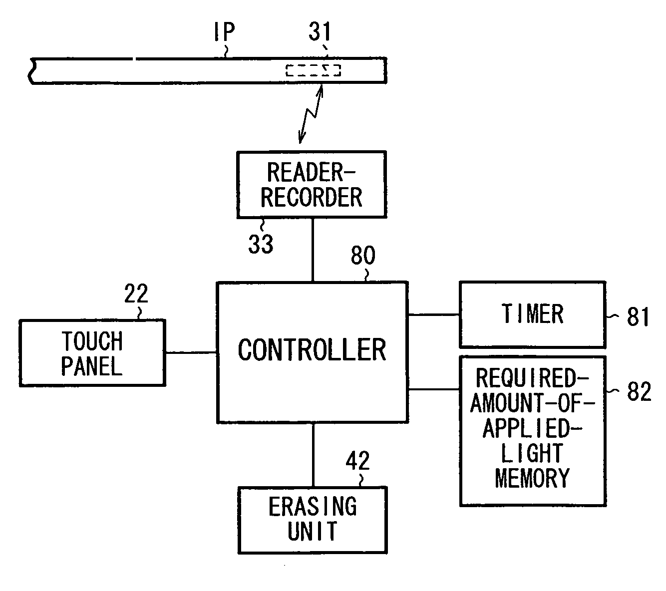
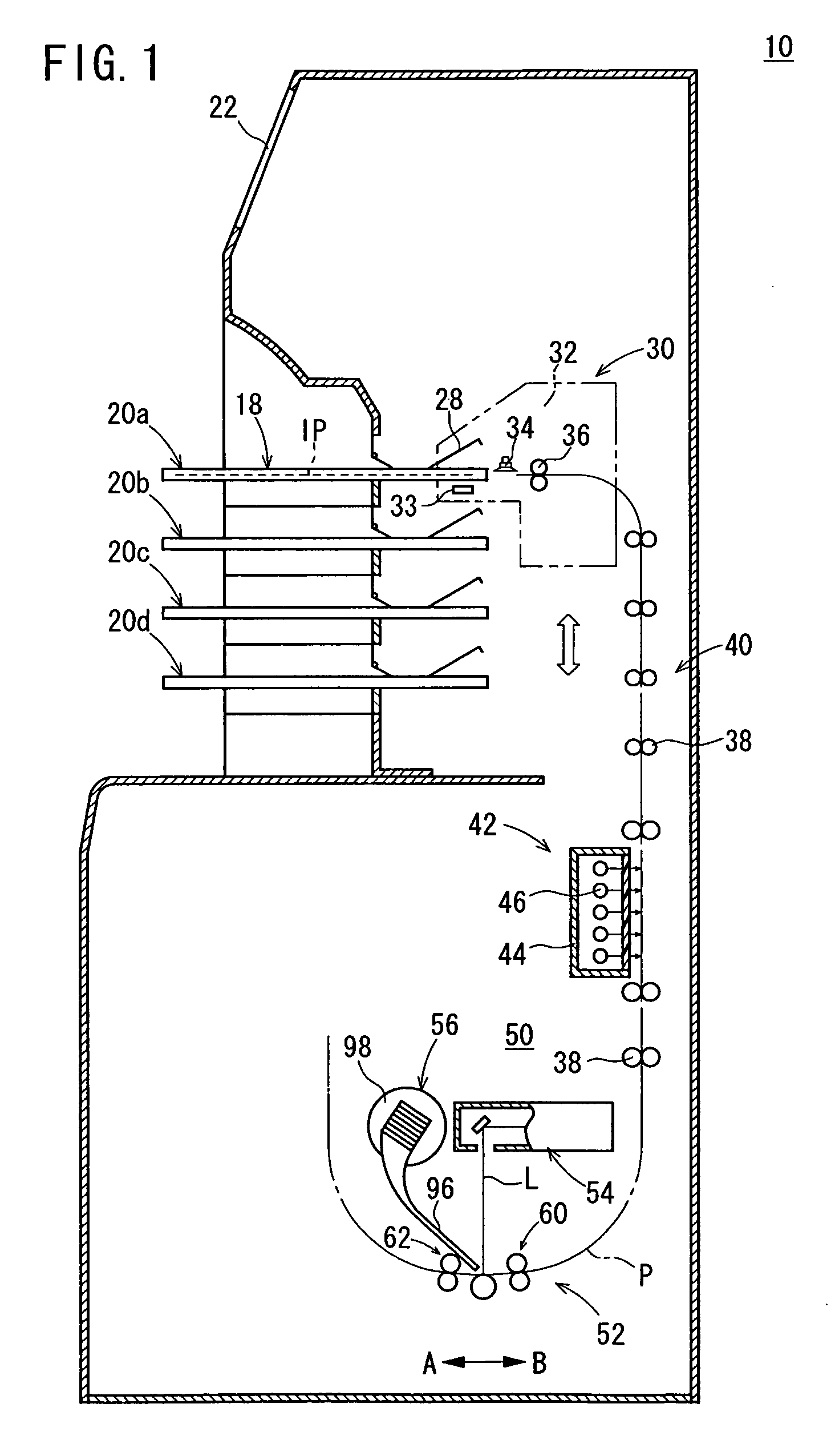
[0018]FIG. 1 shows in vertical cross section an image reading apparatus 10 incorporating an erasing device according to an embodiment of the present invention.

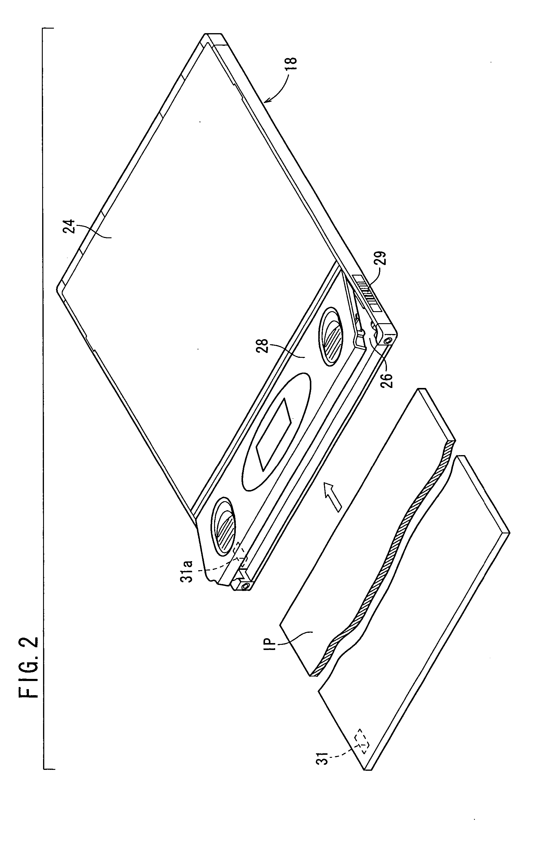
[0019] As shown in FIG. 1, the image reading apparatus 10 has in its upper section a plurality of cassette loaders 20a, 20b, 20c, 20d each loaded with a cassette 18 (see FIG. 2) housing therein a stimulable phosphor sheet IP as a stimulable phosphor panel with the radiation image information of a subject being recorded therein. The image reading apparatus 10 also has a touch panel 22 disposed above the uppermost cassette loader 20a for displaying an operation status and a control procedure of the image reading apparatus 10 and also entering necessary commands.

[0020] The cassette 18 comprises a casing 24 for storing the stimulable phosphor sheet IP therein and a lid 28 openably and closably hinged to the casing 24. When the lid 28 is opened, an opening 26 is defined between the lid 28 and the casing 24 for inserting the stimu...


PUM


Abstract

A preceding erasure time stored in an IC chip embedded in a stimulable phosphor sheet is read in step S3. After radiation image information is read from the stimulable phosphor sheet in step S5, an elapsed time up to the present time is calculated in step S6, and a required amount of erasing light corresponding to the elapsed time is read from a required-amount-of-applied-light memory in step S7. An erasing light application time is calculated from the radiation image information and the read required amount of erasing light in step S8. Erasing light sources are energized for the calculated erasing light application time to apply erasing light to the stimulable phosphor sheet to erase remaining radiation energy therefrom in step S10.

Description

BACKGROUND OF THE INVENTION [0001] 1. Field of the Invention [0002] The present invention relates to an erasing device for applying erasing light to a stimulable phosphor panel to erase radiation energy remaining in the stimulable phosphor panel. [0003] 2. Description of the Related Art [0004] There has heretofore been known a stimulable phosphor which, when exposed to an applied radiation (X-rays, α-rays, β-rays, γ-rays, electron beams, ultraviolet radiation, or the like), stores part of the energy of the radiation, and, when subsequently exposed to applied stimulating rays such as visible light, emits light in proportion to the stored energy of the radiation. A radiation image information recording and reproducing system, which is employed in the art, temporarily records radiation image information of a subject such as a human body on a stimulable phosphor panel having a stimulable phosphor layer. Thereafter, the radiation image information recording and reproducing system applies...

Claims


Application Information

Patent Timeline
Patent Type & Authority Applications(United States)
IPC IPC(8): G03B42/02G03B42/08
CPCG03B42/08
Inventor NAKAJO, MASAKAZUSUZUKI, HIDEKI
Owner FUJIFILM HLDG CORP
Why Eureka
Try Eureka