Method for starting an engine

a technology of engine and starting system, which is applied in the direction of engine starters, machines/engines, output power, etc., can solve the problems of reducing the capacity of the electric machine and the amount of energy consumed by the electric machine reducing the amount of energy applied to start the engine, so as to facilitate engine starting and reduce the amount of energy applied to rotate the engine. , the effect of reducing the amount of tim

Active Publication Date: 2020-12-08
FORD GLOBAL TECH LLC
View PDF5 Cites 5 Cited by
  • Summary
  • Abstract
  • Description
  • Claims
  • Application Information

AI Technical Summary

Benefits of technology

[0002]An internal combustion engine of a vehicle may be cranked via an electric machine to facilitate engine starting. The cranking may include rotating the engine at a speed that is less than an engine idle speed while supplying spark and fuel to the engine. Once combustion is initiated in the engine and the engine accelerates to engine idle speed, electrical power that is supplied to the electric machine may be withdrawn. However, the amount of energy that is applied to rotate the engine may vary from engine start to engine start. In particular, the amount of energy applied to start the engine may depend on the position at which the engine stops, engine temperature, and the amount of time that the engine is cranked via the electric machine before combustion in the engine begins to accelerate the engine as well as other engine and vehicle conditions. However, if the engine may be started in a shorter amount of time and by delivering less energy to rotate the engine via the electric machine, it may be possible to reduce the capacity of the electric machine and an amount of energy that is consumed by the electric machine to start the engine.

Problems solved by technology

However, if the engine may be started in a shorter amount of time and by delivering less energy to rotate the engine via the electric machine, it may be possible to reduce the capacity of the electric machine and an amount of energy that is consumed by the electric machine to start the engine.
Specifically, the approach may reduce an amount of energy applied to start an engine.
Further still, the approach may enable engine starting with lower torque capacity engine starters and lower capacity electric energy storage devices.

Method used


Image

  • Method for starting an engine
  • Method for starting an engine
  • Method for starting an engine

Examples


Embodiment Construction

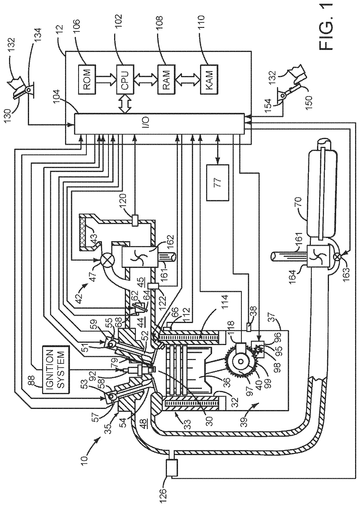
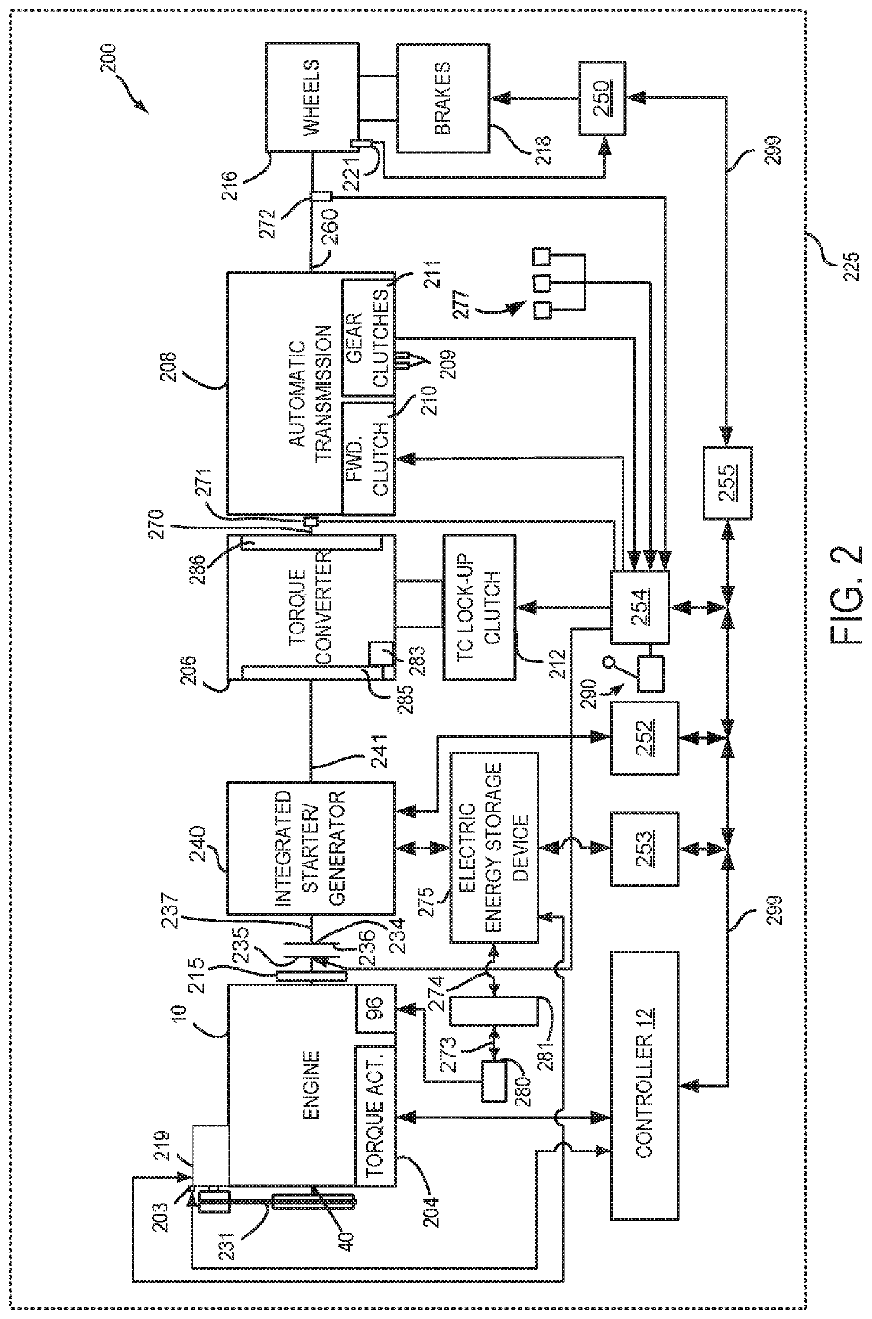
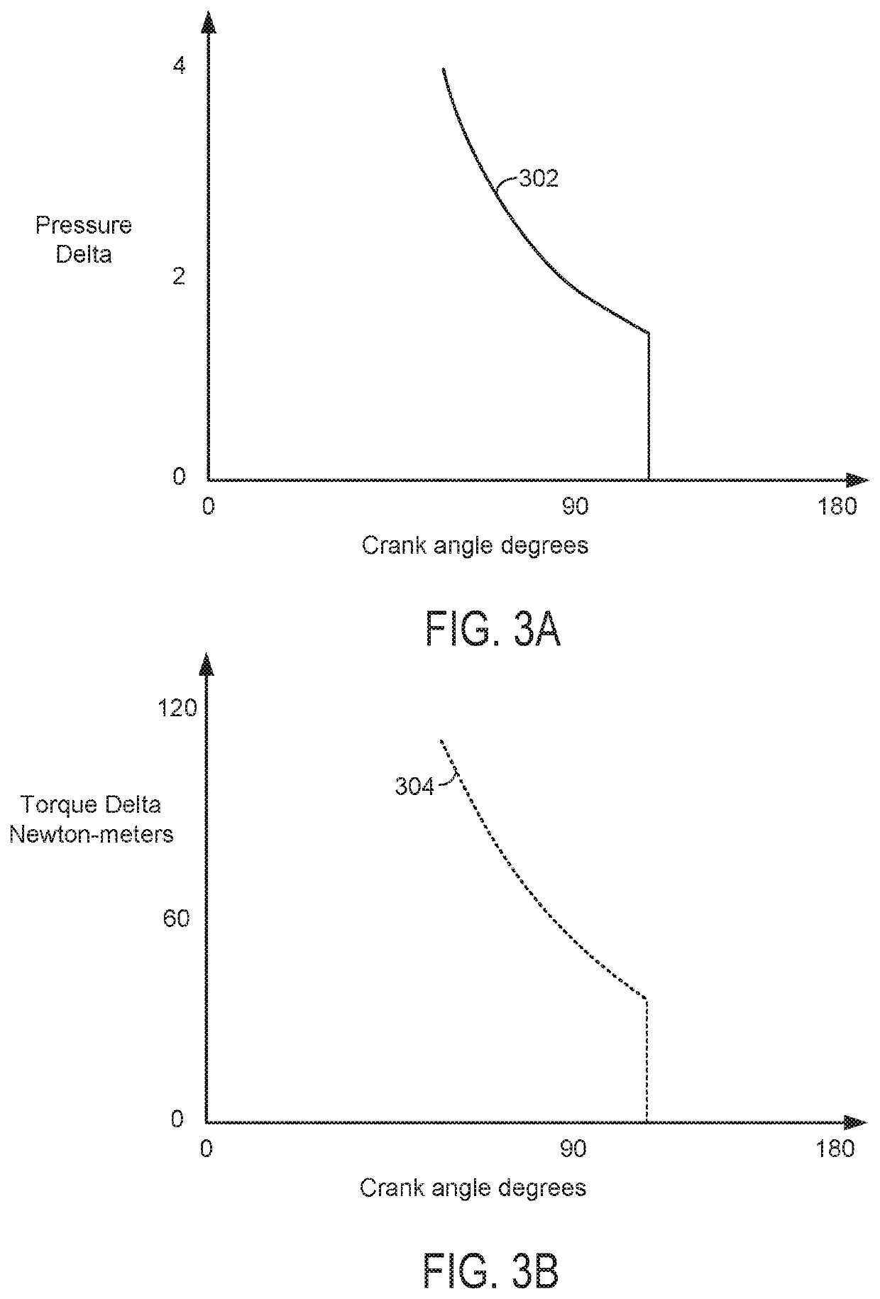
[0013]The present description is related to starting an engine and reducing energy to start the engine. The engine may be of the type shown in FIG. 1. The engine may be included in a driveline or powertrain as shown in FIG. 2. The engine may be directly started or the cranking process may be assessed via initiating expansion stroke combustion. Pressure in engine cylinders and torque generated by the cylinders may follow the trajectories shown in FIGS. 3A-4B. Two engine starting sequences are shown in FIG. 5, and the sequence of FIG. 5 may be generated via the method of FIG. 6. In one example, the method of FIG. 6 adjusts exhaust valve timing of a cylinder such that the exhaust valves open at a crankshaft angle where pressure in the cylinder is substantially equal to pressure in the crankcase so that engine cranking torque may be reduced and engine expansion work may be more fully utilized.

[0014]Referring to FIG. 1, internal combustion engine 10, comprising a plurality of cylinders, ...


PUM


Abstract

A method for starting an engine is disclosed. The method may adjust exhaust valve opening timing of one or more cylinders during a first cycle of an engine since a most recent engine stop to reduce engine cranking work. The method may adjust exhaust valve timing if the engine is directly started or started via an electric machine.

Description

FIELD[0001]The present description relates to methods and a system for starting an engine. The methods and systems may reduce system cost and an amount of energy applied to crank the engine.BACKGROUND AND SUMMARY[0002]An internal combustion engine of a vehicle may be cranked via an electric machine to facilitate engine starting. The cranking may include rotating the engine at a speed that is less than an engine idle speed while supplying spark and fuel to the engine. Once combustion is initiated in the engine and the engine accelerates to engine idle speed, electrical power that is supplied to the electric machine may be withdrawn. However, the amount of energy that is applied to rotate the engine may vary from engine start to engine start. In particular, the amount of energy applied to start the engine may depend on the position at which the engine stops, engine temperature, and the amount of time that the engine is cranked via the electric machine before combustion in the engine b...

Claims


Application Information

Patent Timeline
Patent Type & Authority Patents(United States)
IPC IPC(8): F02N19/00F02M57/04F02N11/08F02M41/14
CPCF02N11/0862F02N19/004F02M57/04F02N2200/025F02M2041/1472F02B77/08F02D13/0249F02N11/08F02N11/0851F02N11/04F02N11/0814F02N2200/041F02N2300/2002
Inventor DOERING, JEFFREY ALLENGIBSON, ALEXANDER O'CONORVANDERWEGE, BRAD ALAN
Owner FORD GLOBAL TECH LLC
Why Eureka
Try Eureka