

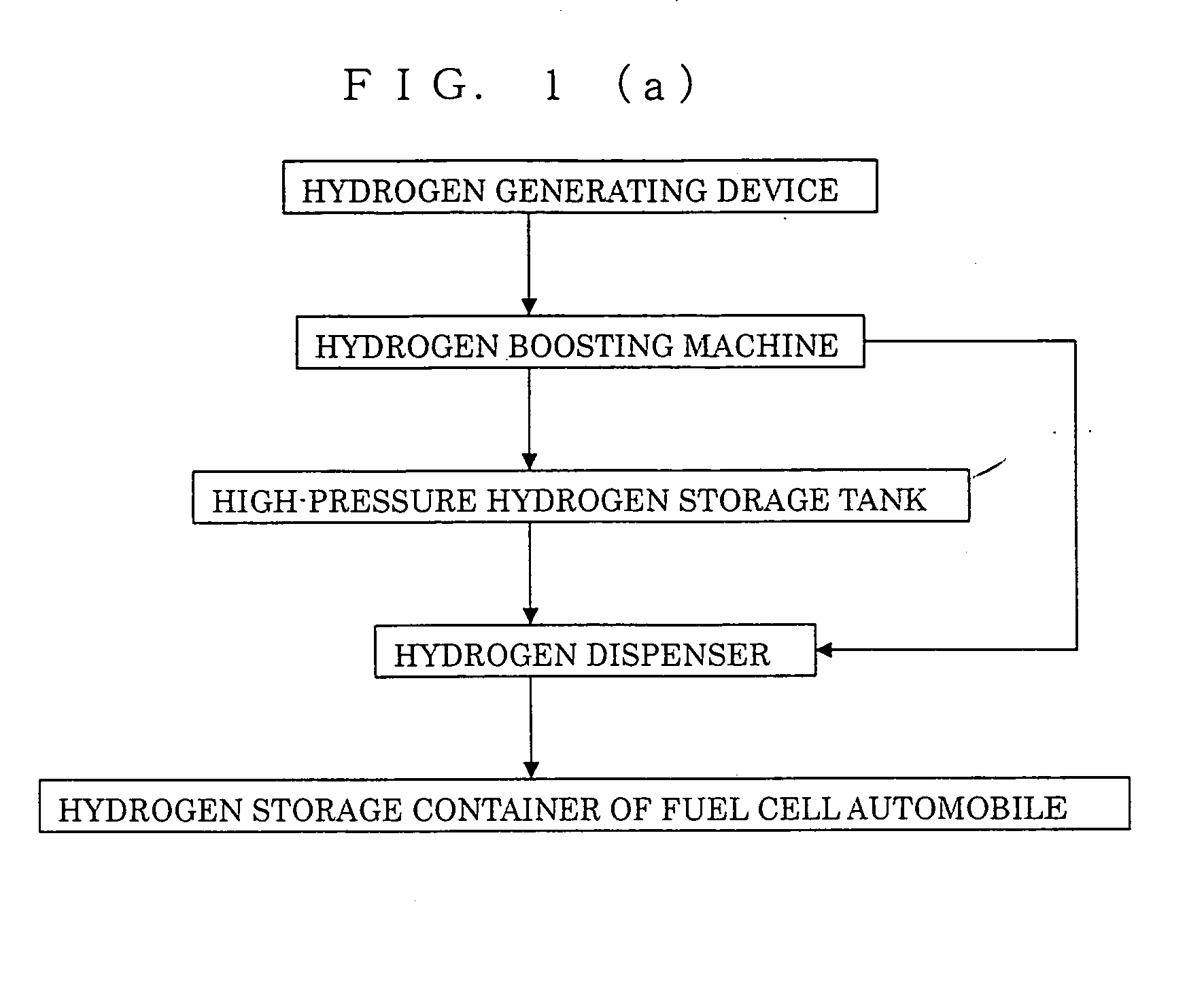
Hydrogen Supply System
a technology of water supply system and hydrogen supply system, which is applied in the direction of transportation hydrogen technology, cell components, electrochemical generators, etc., can solve the problems of high cost of reforming device, inability to improve the wide-area hydrogen supply infrastructure of freely running fuel cell automobiles, and inability to meet the needs of reformers, etc., to achieve the effect of reducing the time required for start and energy amount for raising the temperature of reformers, saving energy costs, and easy supply
- Summary
- Abstract
- Description
- Claims
- Application Information
AI Technical Summary
Benefits of technology
Problems solved by technology
Method used
Image

Examples
example 1
[0230]Illustrative examples of generating hydrogen based on the hydrogen generating device used in the hydrogen supply system (open-circuit condition) as defined by claim 3 of the invention will be presented below.
Hydrogen Generating Example 1-1
[0231]Hydrogen generating cells described in Example 1 (generating examples 1-1 to 1-10) have the same structure as that of representative DMFCs.
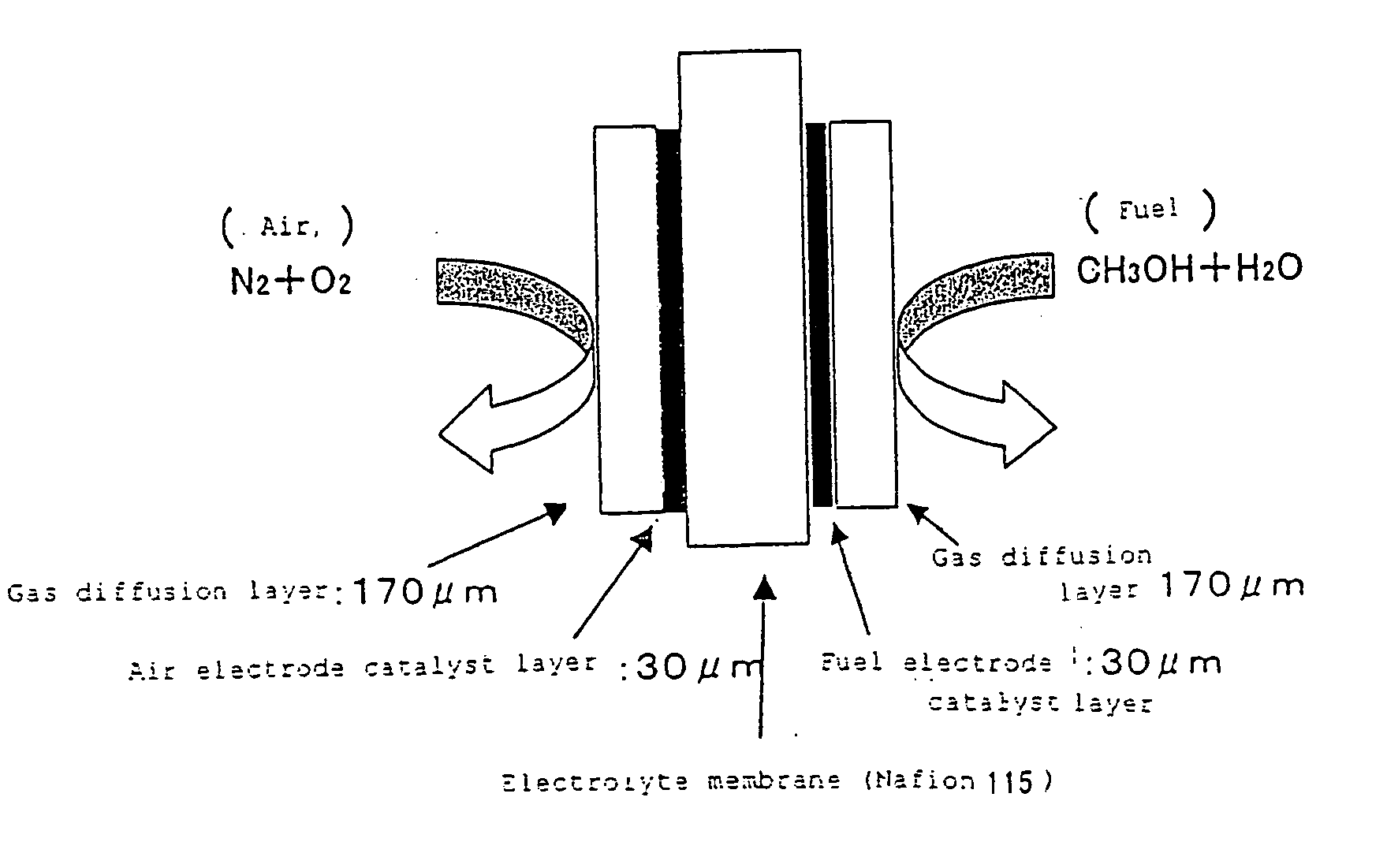
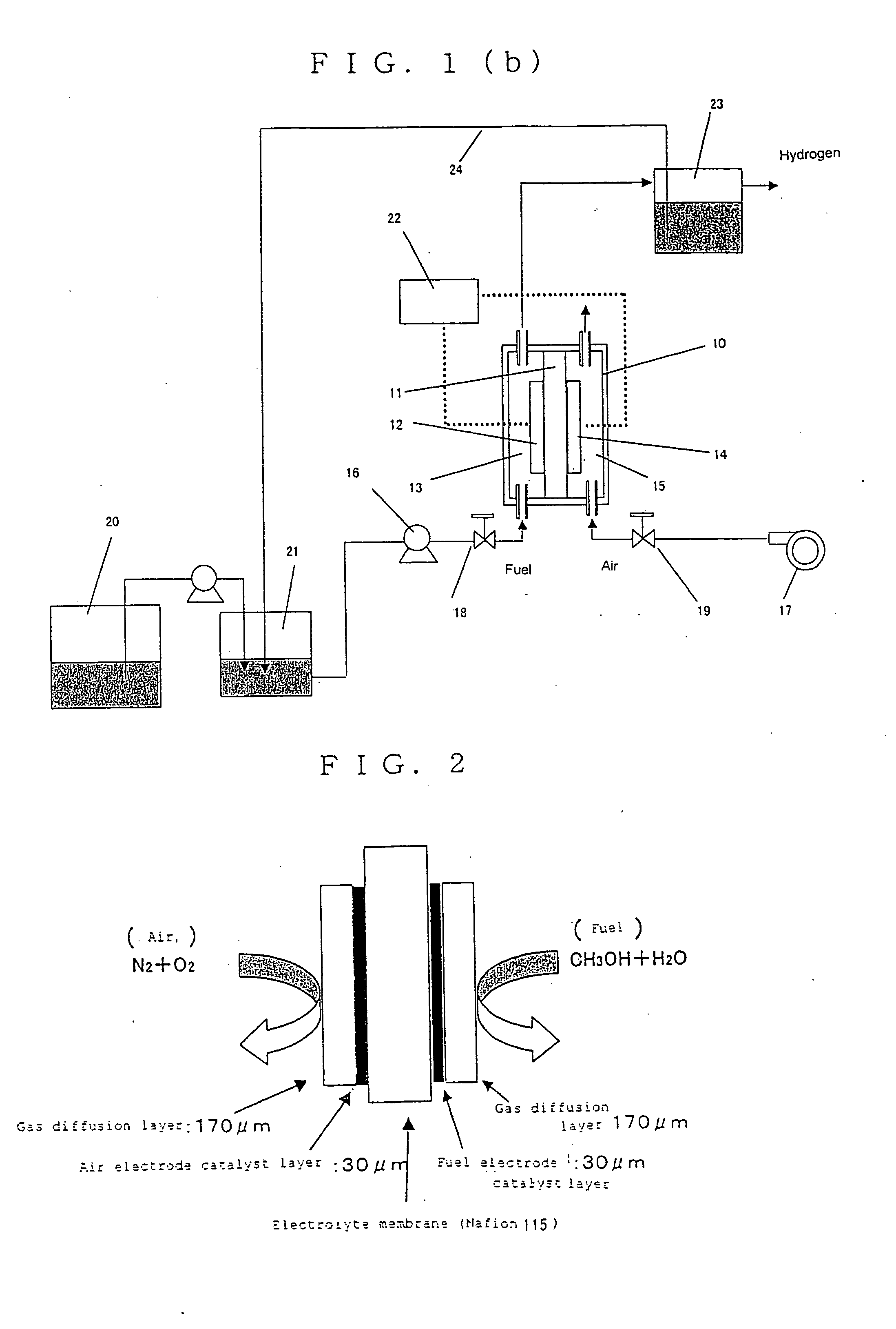
[0232]The structure of the hydrogen generating cell is outlined in FIG. 2.
[0233]The electrolyte membrane consists of a proton conducting electrolyte membrane provided by Dupont (Nafion 115); and the air electrode is obtained by immersing carbon paper (Toray) in a solution where polytetrafluoroethylene is dispersed at 5%, and baking the paper at 360° C. to make it water-repellent, and coating, on one surface of the paper, air electrode catalyst paste comprised of air electrode catalyst (carbon-supported platinum, Tanaka Precious Metal), fine powder of PTFE, and 5% Nafion solution (Aldrich). Thus, the ...
example 2
[0286]Illustrative examples of the hydrogen generating device used in the hydrogen supply system as defined by claim 4 of the invention (discharging condition) will be presented below.
Hydrogen Generating Example 2-1
[0287]The structure of hydrogen generating cells described in Example 2 (illustrative examples 2-1 to 2-8) with means for withdrawing electric energy is outlined in FIG. 21.
[0288]The hydrogen generating cells of Example 2 are the same in structure as those of hydrogen generating example 1-1 except that the cell comprises a fuel electrode as a negative electrode and an air electrode as a positive electrode with means for withdrawing electric energy.
[0289]The hydrogen generating cell was placed in an electric furnace where hot air was circulated. The cell was operated while the temperature (operation temperature) being kept at 50° C. with the flow rate of air to the air electrode kept at 10 to 100 ml / min and the flow of 1M aqueous solution of methanol (fuel) to the fuel ele...
example 3
[0339]Illustrative examples of the hydrogen generating device used in the hydrogen supply system as defined by claim 5 of the invention (charging condition) will be presented below.
Hydrogen Generating Example 3-1
[0340]The structure of hydrogen generating cells described in Example 3 (hydrogen generating examples 3-1 to 3-8) with means for providing electric energy from outside is outlined in FIG. 42.
[0341]The hydrogen generating cells are the same in structure as those of hydrogen generating example 1-1 except that the cell comprises a fuel electrode as cathode and an oxidizing electrode as anode with means for providing electric energy from outside.
[0342]The hydrogen generating cell was placed in an electric furnace where hot air was circulated. The cell was operated while the temperature (operation temperature) being kept at 50° C. with the flow of air to the air electrode kept at 10 to 80 ml / min and the flow of 1M aqueous solution of methanol (fuel) to the fuel electrode kept at ...
PUM
| Property | Measurement | Unit |
|---|---|---|
| voltage | aaaaa | aaaaa |
| voltage | aaaaa | aaaaa |
| voltage | aaaaa | aaaaa |
Abstract
Description
Claims
Application Information